- Cisco Community
- Technology and Support
- Data Center and Cloud
- Data Center and Cloud Knowledge Base
- Datacenter Core and Aggregation Design
- Subscribe to RSS Feed
- Mark as New
- Mark as Read
- Bookmark
- Subscribe
- Printer Friendly Page
- Report Inappropriate Content
- Subscribe to RSS Feed
- Mark as New
- Mark as Read
- Bookmark
- Subscribe
- Printer Friendly Page
- Report Inappropriate Content
12-12-2012 03:21 AM - edited 03-01-2019 05:57 AM
- Introduction
- Layered Datacenter Architecture
- Datacenter Core Layer
- Datacenter Aggregation Layer
- Datacenter Access Layer
- Related Information
Introduction
Datacenter design is based on a proven layered approach. The layered approach is the basic foundation of the DC design that seeks to improve scalability, performance, flexibility, resiliency, and maintenance.
This document describes:
Datacenter Core Layer
Datacenter Aggregation Layer
Datacenter Access Layer
Layered Datacenter Architecture
This design leverages Cisco's best platforms and best practices that deliver flexible and optimal solutions that can easily scale to a large number of physical or virtual servers. The design is also flexible enough to accommodate network virtualization to separate different customers, while including virtualized network services such as virtual firewalls and virtual server load balancers.
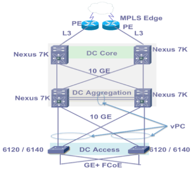
The data center design is based on a three-layer network design model with core, aggregation, and access layers. Each layer has specific requirements and provides different features and functionality.
Datacenter Core Layer
The core layer provides the high-speed packet switching backplane for all flows going in and out of the data center. The core layer provides connectivity to multiple aggregation modules and provides a resilient Layer 3 routed fabric with no single point of failure. The core layer runs an interior routing protocol, such as OSPF or EIGRP, and load balances traffic between the campus core and aggregation layers using Cisco Express Forwarding (CEF)-based hashing algorithms.
The core layer is purely a Layer 3 environment. As a result, the core layer is free of spanning tree and vPC.
Datacenter Aggregation Layer
The aggregation layer is the L3 and L2 boundary for the data center infrastructure. In common designs, the aggregation layer is also the connection point for data center firewalls and other services. Thus, it consolidates L2 traffic in a high-speed packet switching fabric and provides a platform for network- based services at the interface between L2 and L3 in the data center.
This design employs a pair of redundant Cisco Nexus 7010 switches on the aggregation and core layers. Virtual device contexts (VDCs) of the Nexus 7000 switches are utilized in the design to create a pair of aggregation VDC switches and a pair of core VDC switches from two Nexus 7010 switches. The aggregation VDCs supports Layer 2 multi-pathing to the access layers through virtual port-channels (vPCs). Enterprise VLANs having their Layer 3 termination on the SVI interfaces of the Aggregation VDCs, and Hot-Standby router Protocol (HSRP) is utilized to provide the gateway redundancy for the UC applications hosted in the UCS. The UC application traffic destined to Enterprise Cloud to the HSRP address on the Aggregation Layer VDCs. VRF Lite is used between Nexus 7000 core and aggregation VDCs to enable segmentation of enterprise customers hosted on the common physical infrastructure.
Datacenter Access Layer
This is the lowest of the three layers of the architecture, where all servers physically attach to the network. The applications run on B-Series blades in UCS 5108 chassis. In other example, real compute and storage resources attach to the access layer. Generally, this is completely an L2 domain which can have L3 connectivity to limit the broadcast domains. When using L3 at the access layer, it is difficult to use various high availability (HA) features such as VMware HA, NIC teaming, and so on because of IP addressing requirements. It is recommended to use only L2 at the access layer.
At the access layer, connectivity to the SAN must also be considered. The storage path can use Ethernet or Fibre Channel (FC) interfaces. FC interfaces consist of 1/2/4GBps interfaces and connect to a SAN switch, Cisco MDS platform. The back-end high-speed fabric and storage path (10 GE) can also be a common transport medium when IP over Ethernet is used to access storage. In this design SAN is the only recommended storage networking which requires the FC connectivity.
When using UCS 5108 chassis for server connectivity, it is essential to use the Fabric Interconnect 6100. Without the 6100 FI, the fabric extenders on the UCS 5108 chassis cannot be configured and there is no connectivity between the UCS 5108 and the access layer. The FI at the access layer acts as a host switch for the UCS 5108 server chassis; it does not provide any routing capabilities. The connectivity between the access layer switches and the UCS server chassis is based on 10 Gbps Fibre channel over Ethernet (FCoE) links, which carry Ethernet data traffic and FC storage traffic. You should perform some traffic engineering on these links. The storage traffic can cause slow responses for real application data traffic.
In the L2 access layer, redundant pairs of Cisco UCS 6120 switches aggregate VLANs from the Nexus 1000V DVS. FCoE SAN traffic from Virtual machines are handed off as FC traffic to a pair of MDS SAN switches, and then to a pair of storage array controllers. FC expansion modules in the UCS 6120 switch provide SAN interconnects to dual SAN fabrics. The UCS 6120 switches are in NPV mode to interoperate with the SAN fabric.
Related Information
- Mark as Read
- Mark as New
- Bookmark
- Permalink
- Report Inappropriate Content
Thanks for the great piece of info, though it is very helpful to learn DC dynamics.
- Mark as Read
- Mark as New
- Bookmark
- Permalink
- Report Inappropriate Content
Hi,
Good info. I have a question. Since you are using the same physical device (but logically separate using VDCs) in Core and Aggregation layer, is it treated as 3-Tier architecture or collapsed core architecture?
- Mark as Read
- Mark as New
- Bookmark
- Permalink
- Report Inappropriate Content
It's still a 3-Tier architecture, because even though the Nexus 7K switches have two contexts (Aggregation and Core), and they physically reside on the same switch, the VDCs are totally separate "devices", so connecting the Aggregation context to the Core context requires the use of external, physical cabling, just as would be done if the Aggregation and Core switches are separate devices.
So, even though VDCs are used, the contexts should still be considered separate devices from an network architecture perspective.
-rb
- Mark as Read
- Mark as New
- Bookmark
- Permalink
- Report Inappropriate Content
Find answers to your questions by entering keywords or phrases in the Search bar above. New here? Use these resources to familiarize yourself with the community:
