Introduction
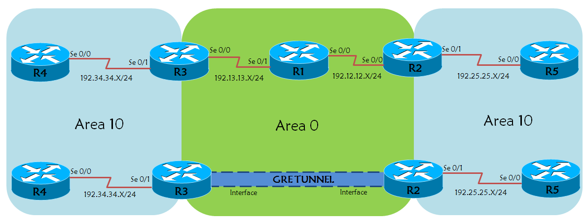
In OSPF, a partitioned area or a split area is not expected. However, in live/some scenario, a network engineer can encounter a situation wherein a fix to split area is needed. In the current topology, Routers R2 and R3 are ABRs (Area Boundary Routers) for partitioned area 10. Each router is configured with Loopback 0 address (x.x.x.x/32, x= Router number), and the loopback is advertised through OSPF.
With basic OSPF configuration, each router can connect and ping the loopback ip address. On further analysis on Router R4, we have a route 5.5.5.5/32 as inter-area route. See the output (Inter-Area in the verification section) of the command “show ip route 5.5.5.5”, it is seen as an inter-area route (i.e LSA Type 3). The desirable/expected result would be, ip route 5.5.5.5 seen as an internal route, which Intra-Area (Type 1 or 2) route on Router R4. Since the route is originating from Area 10, hence it should be seen as an Internal route to R4 and not an external route. Please see the output
Intra-Area in the verification section.
The problem can be approached by two ways:
a) Virtual Links
OR
b)GRE Tunnel
This document focuses on the later part of the solution, Fixing OSPF split Area with GRE Tunnel.
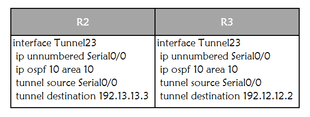
GRE tunnel between the ABRs, R2 and R3. Tunnel Interface 23 is configured using the ip unnumbered command and configuring interface level OSPF command ip ospf 10 area 10, so that the interfaces are part of Area 10 and not Area 0.
Prerequisite
Understanding of OSPF routing protocol
Topology Diagram
Configuration
Basic Connectivity
Basic OSPF Configuration
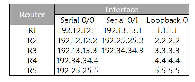
R1R2R3R4R5
router ospf 10 router-id 1.1.1.1 network 1.1.1.1 0.0.0.0 area 0 network 192.12.12.1 0.0.0.0 area 0 network 192.13.13.1 0.0.0.0 area 0 | router ospf 10 router-id 2.2.2.2 network 2.2.2.2 0.0.0.0 area 0 network 192.12.12.2 0.0.0.0 area 0 network 192.25.25.2 0.0.0.0 area 10 | router ospf 10 router-id 3.3.3.3 network 3.3.3.3 0.0.0.0 area 0 network 192.13.13.3 0.0.0.0 area 0 network 192.34.34.3 0.0.0.0 area 10 | router ospf 10 router-id 4.4.4.4 network 4.4.4.4 0.0.0.0 area 10 network 192.34.34.4 0.0.0.0 area 10 | router ospf 10 router-id 5.5.5.5 network 5.5.5.5 0.0.0.0 area 10 network 192.25.25.5 0.0.0.0 area 10 |
GRE Tunnel Interface Configuration
Verification Commands
Inter-Area
Before Tunnel Interface, show ip route 5.5.5.5 as seen on Router R4
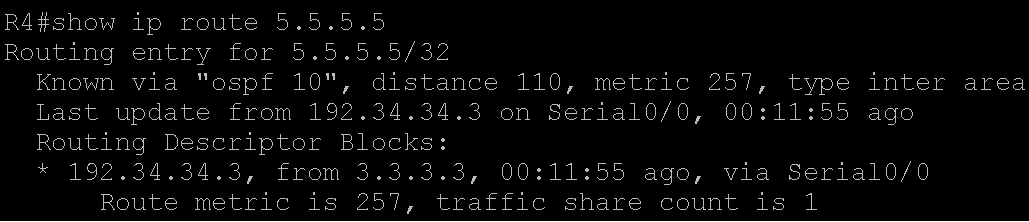
Note: As seen from the output, route 5.5.5.5 is received as an Inter-Area (LSA Type 3) route on R4. R4 assumes that the route originated from a different area.
Intra-Area
After the Tunnel Interface, show ip route 5.5.5.5 as seen on Router R4
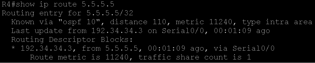
Note: Here R4, assumes that the route 5.5.5.5 is internal or Intra-Area (LSA type 1 or 2) route.
References
OSPF Design Guide
What are OSPF Areas And Virtual Links?
OSPF Configuration Guide