- Cisco Community
- Technology and Support
- Networking
- Routing
- MSTP load balancing
- Subscribe to RSS Feed
- Mark Topic as New
- Mark Topic as Read
- Float this Topic for Current User
- Bookmark
- Subscribe
- Mute
- Printer Friendly Page
- Mark as New
- Bookmark
- Subscribe
- Mute
- Subscribe to RSS Feed
- Permalink
- Report Inappropriate Content
03-01-2013 04:52 AM - edited 03-04-2019 07:10 PM
Dear All,
I have designed in my lab per vlan load failure infrastructure and it works well for me but in our real topology we use MSTP
In both switch'e we receive same vlans and same services I mean one switch for backup purposes and second as active so I want to configure mstp per vlan load failure
I prefer cost based
Any ideas?
Thanks
Kind Regards
Solved! Go to Solution.
- Labels:
-
Other Routing
Accepted Solutions
")
- Mark as New
- Bookmark
- Subscribe
- Mute
- Subscribe to RSS Feed
- Permalink
- Report Inappropriate Content
03-03-2013 09:53 AM
Hello,
The key question here is whether your ISPs provide a transparent Layer2 interconnection between your switches 1 and 2, i.e. whether the ISP cloud behaves like a "cross-over cable" connecting the switches 1 and 2 together, and whether you can pass MSTP BPDUs through this Layer2 interconnect. If your ISPs do this then configuring what you require is simply a matter of modifying the MSTP costs just like you did. However, if the ISPs do not provide such transparent interconnection between switches 1 and 2 then it is simply not possible to accomplish this using MSTP because there is no Layer2 loop, and hence MSTP has nothing to act on - it must leave all ports unblocked for all instances in a loop-free environment.
Can you confirm that the interconnection between switches 1 and 2 as provided by the ISP cloud is a Layer2-transparent VPN capable of passing all your VLANs and MSTP communication?
Best regards,
Peter
- Mark as New
- Bookmark
- Subscribe
- Mute
- Subscribe to RSS Feed
- Permalink
- Report Inappropriate Content
03-01-2013 04:59 AM
Hello,
MSTP was from the very start designed to avoid the per-VLAN paradigm. Instead, MSTP groups VLANs into instances, and then runs in per-instance basis. Whatever MSTP decides with a particular instance, this decision is binding for all VLANs mapped onto that instance.
So if you want to achieve some kind of load sharing then what you need to do is to split your set of VLANs into more instances and configure different MSTP settings for each of these instances. In your network, it does not make sense to create more than 2 MST instances. So I would suggest creating two MST instances, say, 1 and 2, split your VLANs among these two instances (for example, half of your VLANs into instance 1, the other half into instance 2), and then modify the MST instance costs on your interfaces so that instance 1 uses the path via switch 1 while the other instance uses the path via switch 2.
Feel welcome to ask further!
Best regards,
Peter
- Mark as New
- Bookmark
- Subscribe
- Mute
- Subscribe to RSS Feed
- Permalink
- Report Inappropriate Content
03-01-2013 05:31 AM
Dear Peter,
I have already created several instances in our Corporate switching LAN so I want to bind this two sites to our corporate LAN
IT is my core switch config which stand between Corporate and ISP's
spanning-tree mst configuration
name B
instance 1 vlan 59, 128, 191, 352, 406
instance 2 vlan 130, 600-601
instance 3 vlan 9, 100, 300, 302
instance 4 vlan 126-127, 129
instance 5 vlan 160
instance 6 vlan 200
instance 7 vlan 942
instance 8 vlan 58, 143
instance 9 vlan 701
instance 10 vlan 31, 99, 318
!
spanning-tree mst 0 priority 0
spanning-tree mst 3-4 priority 8192
interface GigabitEthernet0/47
description AZ-1
switchport trunk encapsulation dot1q
switchport trunk allowed vlan 2-4
switchport mode trunk
ip arp inspection trust
spanning-tree mst 1 cost 100
spanning-tree mst 2 cost 200
ip dhcp snooping trust
end
Switch#sh run int gi 0/48
Building configuration...
Current configuration : 260 bytes
!
interface GigabitEthernet0/48
description AZ-2
switchport trunk encapsulation dot1q
switchport trunk allowed vlan 2-4
switchport mode trunk
ip arp inspection trust
spanning-tree mst 1 cost 200
spanning-tree mst 2 cost 100
ip dhcp snooping trust
- Mark as New
- Bookmark
- Subscribe
- Mute
- Subscribe to RSS Feed
- Permalink
- Report Inappropriate Content
03-01-2013 06:10 AM
Hello,
Thank you. So according to this configuration, you already have a working MST configuration including a division of VLANs into instances. I also see that some of your ports are already configured with differing MST costs in different instances.
My question is now - what exact assistance do you need? As I do not know your network in detail, I can not give you exact examples of how to configure your switches but all basic commands are already present - especially the spanning-tree mst cost commands that you need to use in your case. What exact guidance are you now seeking for, assuming that this configuration is already in place?
Best regards,
Peter
- Mark as New
- Bookmark
- Subscribe
- Mute
- Subscribe to RSS Feed
- Permalink
- Report Inappropriate Content
03-01-2013 10:20 PM
Dear Peter,
I have two switches located in different places but they have same services from same prividers for backup purposes and I asked to ISP's engineer to loop traffic that I may control it using mstp for load failure
if one failed then other switch wil take over
My question how to control this type of topology using mstp?
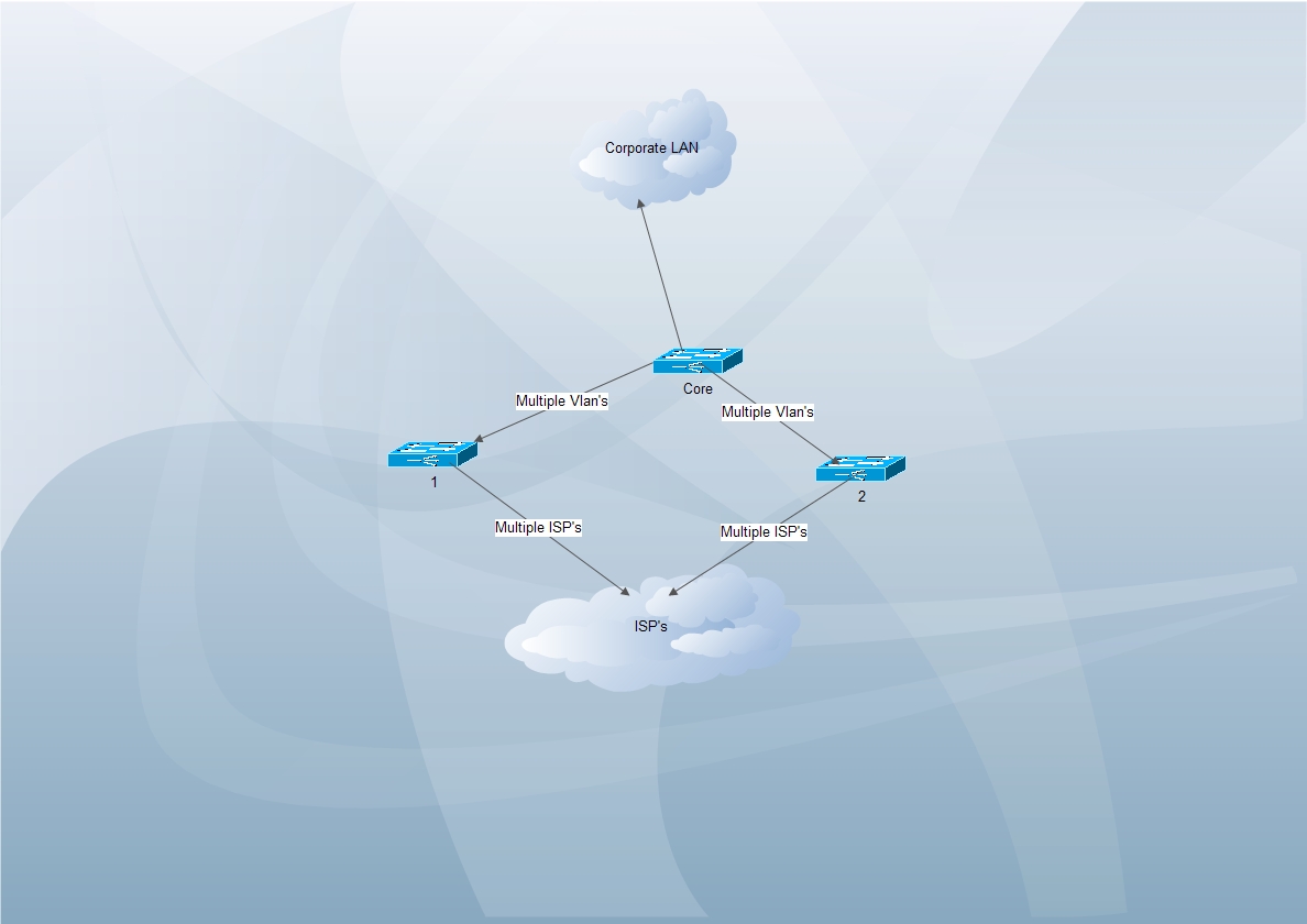
Picture shows that core switch located in our main office and two other switche's -- switch 1 in one place and switch two in other place as I mentioned for load failure
for example I want vlan 2 active in switch 1 but standby in switch 2 also vlan 3 active in switch 2 but standby in switch 1
Switch1--- vlan 2,4 active
switch 2---- vlan 2,4 blocked
Thanks
- Mark as New
- Bookmark
- Subscribe
- Mute
- Subscribe to RSS Feed
- Permalink
- Report Inappropriate Content
03-03-2013 09:53 AM
Hello,
The key question here is whether your ISPs provide a transparent Layer2 interconnection between your switches 1 and 2, i.e. whether the ISP cloud behaves like a "cross-over cable" connecting the switches 1 and 2 together, and whether you can pass MSTP BPDUs through this Layer2 interconnect. If your ISPs do this then configuring what you require is simply a matter of modifying the MSTP costs just like you did. However, if the ISPs do not provide such transparent interconnection between switches 1 and 2 then it is simply not possible to accomplish this using MSTP because there is no Layer2 loop, and hence MSTP has nothing to act on - it must leave all ports unblocked for all instances in a loop-free environment.
Can you confirm that the interconnection between switches 1 and 2 as provided by the ISP cloud is a Layer2-transparent VPN capable of passing all your VLANs and MSTP communication?
Best regards,
Peter
- Mark as New
- Bookmark
- Subscribe
- Mute
- Subscribe to RSS Feed
- Permalink
- Report Inappropriate Content
03-04-2013 02:34 AM
Dear Peter,
Lets think that switch one working enviroment I mean it actually working infrastucture that pases all vlan ann services coming from different ISP's
and switch 2 is new installed so I have tested Loop exist between me and ISP because when I connected switch 2 there was loop and both ISP and we experienced problems )
I am testing it only with one isp for now.
I have tested switch 2 when turning off switch 1 uplink in ISP side services are working in switch 2
I mean virtually loop exist but when I tried to test mstp as you said it didn't work because we experienced loop
what do you think is there missing something >?
Thanks
- Mark as New
- Bookmark
- Subscribe
- Mute
- Subscribe to RSS Feed
- Permalink
- Report Inappropriate Content
03-06-2013 05:29 AM
Dear Peter,
When I converting span-tree to rapi-pvst or pvst it is working as expected but in mstp mode it doesn't
Thanks
- Mark as New
- Bookmark
- Subscribe
- Mute
- Subscribe to RSS Feed
- Permalink
- Report Inappropriate Content
03-08-2013 01:43 PM
Hello my friend,
So when you start MSTP, what exactly goes wrong? Do you get switching loops? Is the traffic not load balanced although according to the MST settings, it should?
Best regards,
Peter
- Mark as New
- Bookmark
- Subscribe
- Mute
- Subscribe to RSS Feed
- Permalink
- Report Inappropriate Content
03-10-2013 11:26 PM
Dear Peter,
yes lswitching loop occured
and mstp doesn't block vlan that has higher cost
but when switching mstp to rpvst it works as expected
Thanks
- Mark as New
- Bookmark
- Subscribe
- Mute
- Subscribe to RSS Feed
- Permalink
- Report Inappropriate Content
03-11-2013 06:34 PM
Hello,
Hmmm. Strange. This sounds as if your service provider was not passing the MST BPDUs through its cloud. It is quite common that providers of L2VPN services do not pass regular Layer2 control traffic such as standardized STP, RSTP or MSTP. The reason RPVST+ works is most probably because it uses a different destination MAC address that does not match the address used by STP/RSTP/MSTP and thus the provider simply considers the RPVST+ to be a multicast application.
Please ask your VPN operator very clearly if he currently allows MSTP BPDUs to be carried through his network so that they can cross the VPN.
Best regards,
Peter
- Mark as New
- Bookmark
- Subscribe
- Mute
- Subscribe to RSS Feed
- Permalink
- Report Inappropriate Content
03-12-2013 12:08 AM
Dear Peter,
I have emulated this topology in my lab.
core sw. 3560x
sw1-2960------ sw2-2960
ISP side web sw with rstp support
in my lab i have emulated this topology and result was unsuccesful
All sw are in one mstp region except isp side
what should be done to 
- Mark as New
- Bookmark
- Subscribe
- Mute
- Subscribe to RSS Feed
- Permalink
- Report Inappropriate Content
03-13-2013 05:37 AM
Hello,
It is good that you have tried to configure a similar topology in your lab. Sadly, unless you precisely know what the ISP is doing you can not realistically emulate it on your web-based ISP switch.
To me, it looks like your ISP is not transporting your MST BPDUs over his network. PVST+ and RPVST+ did go through and the switches avoided the loop. But you've told me yourself that after you activated the MSTP, you had a loop - I assume it closed itself through the provider's network.
So I repeat my question: is your ISP carrying your MST BPDUs between your sites? Can you ask him to perform MSTP BPDU tunneling?
Best regards,
Peter
- Mark as New
- Bookmark
- Subscribe
- Mute
- Subscribe to RSS Feed
- Permalink
- Report Inappropriate Content
03-16-2013 02:41 AM
Dear Peter,
Is there any other method for this kind of topology?
Thanks
- Mark as New
- Bookmark
- Subscribe
- Mute
- Subscribe to RSS Feed
- Permalink
- Report Inappropriate Content
03-16-2013 01:53 PM
Hello,
Hm, you have said RSTP works for you. Would it be acceptable for you to use RSTP, then?
Best regards,
Peter
Discover and save your favorite ideas. Come back to expert answers, step-by-step guides, recent topics, and more.
New here? Get started with these tips. How to use Community New member guide