- Cisco Community
- Technology and Support
- Networking
- Routing
- Routing: LAN Uplink routing issue.
- Subscribe to RSS Feed
- Mark Topic as New
- Mark Topic as Read
- Float this Topic for Current User
- Bookmark
- Subscribe
- Mute
- Printer Friendly Page
Routing: LAN Uplink routing issue.
- Mark as New
- Bookmark
- Subscribe
- Mute
- Subscribe to RSS Feed
- Permalink
- Report Inappropriate Content
12-13-2011 03:08 PM - edited 03-04-2019 02:37 PM
Hi all,
I have finished creating a new layer 3 switching environment at work which is working well but is not considered production yet. While we are not ready to fully cut over to the new LAN, we do need to make that network accessible from the current production LAN. It appears that I have the new LAN partially accessible but only one direction.
Symptoms -
- From the legacy network, I am able to ping any IP within the new LAN
- From a switch in the new LAN, I can ping any address in the legacy LAN
- From a host within a VLAN from the new network, I CANNOT ping hosts by IP in the legacy network. Trace route tests never pass the switch.
Legacy network -
192.137.0.0 /23
I have the routes for all new networks added in our existing gateway which happens to be an IPCop device. The IPCop device has an IP of 192.137.0.152.
New Network -
192.168.0.0 /21
My new LAN switch that I am uplinking into the legacy network -
- IP Routing is turned up obviously since all of the VLANs are working.
- I configured the Legacy VLAN on the new switch with a VLAN interface which is 192.137.0.35.
- I configured an interface within the Legacy VLAN on the new switch, so now I can ping 192.137.0.35.
- Then I set my default route on the new switch set to the IPCop gateway of 192.137.0.152. (ip route 0.0.0.0 0.0.0.0 192.137.0.152)
So in theory it seems like everything is almost working but for some reason hosts within any new VLAN in the new switch are not being passed into the legacy network.
Can anyone shed some light on what I am missing? It is probably something stupid I am overlooking.
- Labels:
-
Other Routing
- Mark as New
- Bookmark
- Subscribe
- Mute
- Subscribe to RSS Feed
- Permalink
- Report Inappropriate Content
12-13-2011 04:24 PM
Hi James,
If you can ping from the switch or router from the legacy to the new network and vice versa, then your routing is working. If you cannot ping from host to host, check to make sure each PC had the correct default gateway. Also check the PCs to make sure there is no firewall software is installed to prevent them from being pinged.
If these suggestions don't help, can you provide a simple diagram showing how everything connects and which device is layer-2 and which layer-3?
HTH
- Mark as New
- Bookmark
- Subscribe
- Mute
- Subscribe to RSS Feed
- Permalink
- Report Inappropriate Content
12-13-2011 04:53 PM
James Allen wrote:
Hi all,
I have finished creating a new layer 3 switching environment at work which is working well but is not considered production yet. While we are not ready to fully cut over to the new LAN, we do need to make that network accessible from the current production LAN. It appears that I have the new LAN partially accessible but only one direction.
Symptoms -
- From the legacy network, I am able to ping any IP within the new LAN
- From a switch in the new LAN, I can ping any address in the legacy LAN
- From a host within a VLAN from the new network, I CANNOT ping hosts by IP in the legacy network. Trace route tests never pass the switch.
Legacy network -
192.137.0.0 /23
I have the routes for all new networks added in our existing gateway which happens to be an IPCop device. The IPCop device has an IP of 192.137.0.152.
New Network -
192.168.0.0 /21
My new LAN switch that I am uplinking into the legacy network -
- IP Routing is turned up obviously since all of the VLANs are working.
- I configured the Legacy VLAN on the new switch with a VLAN interface which is 192.137.0.35.
- I configured an interface within the Legacy VLAN on the new switch, so now I can ping 192.137.0.35.
- Then I set my default route on the new switch set to the IPCop gateway of 192.137.0.152. (ip route 0.0.0.0 0.0.0.0 192.137.0.152)
So in theory it seems like everything is almost working but for some reason hosts within any new VLAN in the new switch are not being passed into the legacy network.
Can anyone shed some light on what I am missing? It is probably something stupid I am overlooking.
James.
You have the "new" switch set with a default route pointing to 192.137.0.152 from an interface of 192.137.0.35 - is that link a layer 2 (all ports in the same VLAN with SVI's) link, or layer 3 (routed link, with an IP address configured on the physical interface).
My point is - what's the IP address of the port that 192.137.0.35 connects to? Is it a layer 3 port with its own address, or a layer 2 port in the same VLAN as 192.137.0.152?
The fact that you can PING from the new switch to the legacy network doesn't really show much since if it's a layer 2 network, the source of the PING packet will be the switch (192.137.0.35), and since it's in the "same" network as the IPCop device it'l simply be classed as directly connected.
The fact that you can communicate between VLAN's on your "new" switch indicates that there is routing within that switch - so something is either preventing the packets to other destinations (outbound access list?), or the next hop for outbound traffic is wrong.
What happens if you try to tracetroute IN to the new network from a node on the legacy network? Where does the trace stop?
Can you indicate what kind of devices you have, and post sanitised configs of the relevant interfaces (the linke, the SVI's etc) and the routing tables in your new switch?
Cheers.
- Mark as New
- Bookmark
- Subscribe
- Mute
- Subscribe to RSS Feed
- Permalink
- Report Inappropriate Content
12-14-2011 08:21 AM
Thanks for the replies guys. After a bit of digging, it appears that the IPCop device is causing the issue. I found that I was able to ping the 192.137.0.152 from a host within a VLAN in my new switch but that device is not forwarding it out correctly.
One thing I did think about last night was, why am I pointing to 192.137.0.152 at all to refer gateway functions? Currently, I do not need any hosts in the new network to get on the internet so in theory, shouldn't I be able to just get rid of the default route to the 192.137.0.152 IPCop device and my switch would already just work and be able to communicate into the legacy network? And now since not referring to a device that is setup weird, I can just use the interface I dropped into that LAN?
- Mark as New
- Bookmark
- Subscribe
- Mute
- Subscribe to RSS Feed
- Permalink
- Report Inappropriate Content
12-14-2011 08:43 AM
Hmm, that didn't seem to work. I would have thought that the VLAN I created would have just send traffic out for that network and since it was in the same LAN that it would work.
- Mark as New
- Bookmark
- Subscribe
- Mute
- Subscribe to RSS Feed
- Permalink
- Report Inappropriate Content
12-14-2011 10:04 AM
Hi,
for devices in 2 different VLANS to cummunicate you need a L3 device.
Regards.
Alain
- Mark as New
- Bookmark
- Subscribe
- Mute
- Subscribe to RSS Feed
- Permalink
- Report Inappropriate Content
12-14-2011 10:12 AM
I get that I need a layer 3 device which is why my new switch has a VLAN and VLAN interface on the same network as the legacy network. I would just think that since I have a port assigned to that VLAN on the new switch it would be able to talk with everything else on the same net out of that interface.
- Mark as New
- Bookmark
- Subscribe
- Mute
- Subscribe to RSS Feed
- Permalink
- Report Inappropriate Content
12-14-2011 10:28 AM
Posting a diagram per Darren's request -
http://i117.photobucket.com/albums/o49/0xploit/RoutingIssue-1.jpg
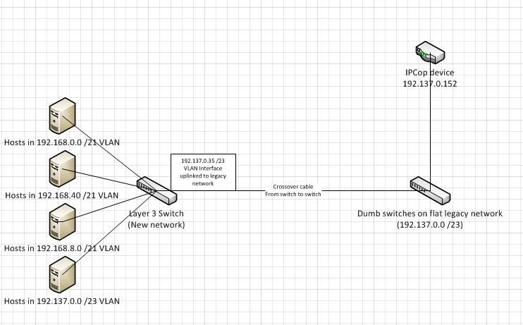
Trying to get the routing tables and other stuff as well.
- Mark as New
- Bookmark
- Subscribe
- Mute
- Subscribe to RSS Feed
- Permalink
- Report Inappropriate Content
12-14-2011 10:37 AM
Here is my config on my new switch - (Uplink to my legacy network is GI1/0/24)
!
version 15.0
no service pad
service timestamps debug datetime msec
service timestamps log datetime msec
no service password-encryption
!
hostname Switch01
!
boot-start-marker
boot-end-marker
!
no aaa new-model
clock timezone PST -8 0
clock summer-time PDT recurring
switch 1 provision ws-c3750x-24
system mtu routing 1500
ip routing
!
!
ip domain-name domain.com
ip name-server 192.137.0.158
ip name-server 192.137.0.170
cluster enable ORCluster 0
!
!
!
spanning-tree mode pvst
spanning-tree extend system-id
!
!
!
!
vlan internal allocation policy ascending
!
!
!
!
!
!
interface Port-channel1
switchport trunk encapsulation dot1q
switchport mode trunk
!
interface FastEthernet0
no ip address
no ip route-cache
no ip mroute-cache
shutdown
!
interface GigabitEthernet1/0/1
switchport access vlan 104
!
interface GigabitEthernet1/0/2
switchport access vlan 104
!
interface GigabitEthernet1/0/3
switchport access vlan 101
!
interface GigabitEthernet1/0/4
switchport access vlan 101
!
interface GigabitEthernet1/0/5
switchport access vlan 101
!
interface GigabitEthernet1/0/6
switchport access vlan 101
!
interface GigabitEthernet1/0/7
switchport access vlan 101
!
interface GigabitEthernet1/0/8
switchport access vlan 101
!
interface GigabitEthernet1/0/9
switchport access vlan 106
!
interface GigabitEthernet1/0/10
description ORPXEN02 DRAC
switchport access vlan 106
!
interface GigabitEthernet1/0/11
switchport access vlan 106
!
interface GigabitEthernet1/0/12
switchport access vlan 106
!
interface GigabitEthernet1/0/13
switchport access vlan 106
!
interface GigabitEthernet1/0/14
switchport access vlan 106
!
interface GigabitEthernet1/0/15
switchport access vlan 101
!
interface GigabitEthernet1/0/16
switchport access vlan 101
!
interface GigabitEthernet1/0/17
switchport access vlan 101
!
interface GigabitEthernet1/0/18
switchport access vlan 104
switchport trunk encapsulation dot1q
switchport mode trunk
!
interface GigabitEthernet1/0/19
switchport access vlan 104
switchport trunk encapsulation dot1q
switchport mode trunk
!
interface GigabitEthernet1/0/20
switchport access vlan 104
switchport trunk encapsulation dot1q
switchport mode trunk
!
interface GigabitEthernet1/0/21
switchport access vlan 104
switchport trunk encapsulation dot1q
switchport mode trunk
!
interface GigabitEthernet1/0/22
switchport access vlan 104
switchport trunk encapsulation dot1q
switchport mode trunk
!
interface GigabitEthernet1/0/23
switchport access vlan 104
!
interface GigabitEthernet1/0/24
switchport access vlan 110
!
interface GigabitEthernet1/1/1
switchport trunk encapsulation dot1q
switchport mode trunk
channel-group 1 mode on
!
interface GigabitEthernet1/1/2
switchport trunk encapsulation dot1q
switchport mode trunk
channel-group 1 mode on
!
interface GigabitEthernet1/1/3
!
interface GigabitEthernet1/1/4
!
interface TenGigabitEthernet1/1/1
!
interface TenGigabitEthernet1/1/2
!
interface Vlan1
no ip address
shutdown
!
interface Vlan101
description Server_Network
ip address 192.168.1.1 255.255.248.0
standby 1 ip 192.168.1.254
standby 1 priority 10
standby 1 preempt
!
interface Vlan102
description Client_Access
ip address 192.168.8.1 255.255.248.0
ip helper-address 192.137.0.158
ip helper-address 192.137.0.170
standby 2 ip 192.168.8.254
standby 2 priority 10
standby 2 preempt
!
interface Vlan103
description Finance_VLAN
ip address 192.168.16.1 255.255.248.0
ip helper-address 192.137.0.158
ip helper-address 192.137.0.170
standby 3 ip 192.168.16.254
standby 3 priority 10
standby 3 preempt
!
interface Vlan106
description Management_Network
ip address 192.168.40.1 255.255.248.0
standby 6 ip 192.168.40.254
standby 6 priority 10
standby 6 preempt
!
interface Vlan108
description DMZ
ip address 192.168.56.1 255.255.248.0
standby 6 ip 192.168.56.254
standby 6 priority 10
standby 6 preempt
!
interface Vlan110
description Legacy
ip address 192.137.0.34 255.255.254.0
standby 6 ip 192.137.0.35
standby 6 priority 10
standby 6 preempt
!
ip http server
ip http secure-server
!
!
!
ip sla enable reaction-alerts
logging esm config
snmp-server community public RO
snmp-server community private RW
!
!
line con 0
line vty 0 4
***** *******
login
length 0
line vty 5 15
***** ******
login
!
end
!
version 15.0
no service pad
service timestamps debug datetime msec
service timestamps log datetime msec
no service password-encryption
!
hostname Switch01
!
boot-start-marker
boot-end-marker
!
no aaa new-model
clock timezone PST -8 0
clock summer-time PDT recurring
switch 1 provision ws-c3750x-24
system mtu routing 1500
ip routing
!
!
ip domain-name domain.com
ip name-server 192.137.0.158
ip name-server 192.137.0.170
cluster enable ORCluster 0
!
!
!
spanning-tree mode pvst
spanning-tree extend system-id
!
!
!
!
vlan internal allocation policy ascending
!
!
!
!
!
!
interface Port-channel1
switchport trunk encapsulation dot1q
switchport mode trunk
!
interface FastEthernet0
no ip address
no ip route-cache
no ip mroute-cache
shutdown
!
interface GigabitEthernet1/0/1
switchport access vlan 104
!
interface GigabitEthernet1/0/2
switchport access vlan 104
!
interface GigabitEthernet1/0/3
switchport access vlan 101
!
interface GigabitEthernet1/0/4
switchport access vlan 101
!
interface GigabitEthernet1/0/5
switchport access vlan 101
!
interface GigabitEthernet1/0/6
switchport access vlan 101
!
interface GigabitEthernet1/0/7
switchport access vlan 101
!
interface GigabitEthernet1/0/8
switchport access vlan 101
!
interface GigabitEthernet1/0/9
switchport access vlan 106
!
interface GigabitEthernet1/0/10
description ORPXEN02 DRAC
switchport access vlan 106
!
interface GigabitEthernet1/0/11
switchport access vlan 106
!
interface GigabitEthernet1/0/12
switchport access vlan 106
!
interface GigabitEthernet1/0/13
switchport access vlan 106
!
interface GigabitEthernet1/0/14
switchport access vlan 106
!
interface GigabitEthernet1/0/15
switchport access vlan 101
!
interface GigabitEthernet1/0/16
switchport access vlan 101
!
interface GigabitEthernet1/0/17
switchport access vlan 101
!
interface GigabitEthernet1/0/18
switchport access vlan 104
switchport trunk encapsulation dot1q
switchport mode trunk
!
interface GigabitEthernet1/0/19
switchport access vlan 104
switchport trunk encapsulation dot1q
switchport mode trunk
!
interface GigabitEthernet1/0/20
switchport access vlan 104
switchport trunk encapsulation dot1q
switchport mode trunk
!
interface GigabitEthernet1/0/21
switchport access vlan 104
switchport trunk encapsulation dot1q
switchport mode trunk
!
interface GigabitEthernet1/0/22
switchport access vlan 104
switchport trunk encapsulation dot1q
switchport mode trunk
!
interface GigabitEthernet1/0/23
switchport access vlan 104
!
interface GigabitEthernet1/0/24
switchport access vlan 110
!
interface GigabitEthernet1/1/1
switchport trunk encapsulation dot1q
switchport mode trunk
channel-group 1 mode on
!
interface GigabitEthernet1/1/2
switchport trunk encapsulation dot1q
switchport mode trunk
channel-group 1 mode on
!
interface GigabitEthernet1/1/3
!
interface GigabitEthernet1/1/4
!
interface TenGigabitEthernet1/1/1
!
interface TenGigabitEthernet1/1/2
!
interface Vlan1
no ip address
shutdown
!
interface Vlan101
description Server_Network
ip address 192.168.1.1 255.255.248.0
standby 1 ip 192.168.1.254
standby 1 priority 10
standby 1 preempt
!
interface Vlan102
description Client_Access
ip address 192.168.8.1 255.255.248.0
ip helper-address 192.137.0.158
ip helper-address 192.137.0.170
standby 2 ip 192.168.8.254
standby 2 priority 10
standby 2 preempt
!
interface Vlan103
description Finance_VLAN
ip address 192.168.16.1 255.255.248.0
ip helper-address 192.137.0.158
ip helper-address 192.137.0.170
standby 3 ip 192.168.16.254
standby 3 priority 10
standby 3 preempt
!
interface Vlan106
description Management_Network
ip address 192.168.40.1 255.255.248.0
standby 6 ip 192.168.40.254
standby 6 priority 10
standby 6 preempt
!
interface Vlan108
description DMZ
ip address 192.168.56.1 255.255.248.0
standby 6 ip 192.168.56.254
standby 6 priority 10
standby 6 preempt
!
interface Vlan110
description Legacy
ip address 192.137.0.34 255.255.254.0
standby 6 ip 192.137.0.35
standby 6 priority 10
standby 6 preempt
!
ip http server
ip http secure-server
!
!
!
ip sla enable reaction-alerts
logging esm config
snmp-server community public RO
snmp-server community private RW
!
!
line con 0
line vty 0 4
***** *******
login
length 0
line vty 5 15
***** ******
login
!
end
- Mark as New
- Bookmark
- Subscribe
- Mute
- Subscribe to RSS Feed
- Permalink
- Report Inappropriate Content
12-14-2011 10:43 AM
Here is the output of sh ip route -
Gateway of last resort is not set
C 192.137.0.0/23 is directly connected, Vlan110
192.137.0.0/32 is subnetted, 1 subnets
L 192.137.0.34 is directly connected, Vlan110
C 192.168.0.0/21 is directly connected, Vlan101
192.168.1.0/32 is subnetted, 1 subnets
L 192.168.1.1 is directly connected, Vlan101
C 192.168.8.0/21 is directly connected, Vlan102
192.168.8.0/32 is subnetted, 1 subnets
L 192.168.8.1 is directly connected, Vlan102
C 192.168.16.0/21 is directly connected, Vlan103
192.168.16.0/32 is subnetted, 1 subnets
L 192.168.16.1 is directly connected, Vlan103
C 192.168.40.0/21 is directly connected, Vlan106
192.168.40.0/32 is subnetted, 1 subnets
L 192.168.40.1 is directly connected, Vlan106
C 192.168.56.0/21 is directly connected, Vlan108
192.168.56.0/32 is subnetted, 1 subnets
L 192.168.56.1 is directly connected, Vlan108
- Mark as New
- Bookmark
- Subscribe
- Mute
- Subscribe to RSS Feed
- Permalink
- Report Inappropriate Content
12-14-2011 10:55 AM
Also, here is the alternate routing config I had which wasn't working either because of the IPCop device -
Gateway of last resort is 192.137.0.152 to network 0.0.0.0
S* 0.0.0.0/0 [1/0] via 192.137.0.152
C 192.137.0.0/23 is directly connected, Vlan110
192.137.0.0/32 is subnetted, 1 subnets
L 192.137.0.34 is directly connected, Vlan110
C 192.168.0.0/21 is directly connected, Vlan101
192.168.1.0/32 is subnetted, 1 subnets
L 192.168.1.1 is directly connected, Vlan101
C 192.168.8.0/21 is directly connected, Vlan102
192.168.8.0/32 is subnetted, 1 subnets
L 192.168.8.1 is directly connected, Vlan102
C 192.168.16.0/21 is directly connected, Vlan103
192.168.16.0/32 is subnetted, 1 subnets
L 192.168.16.1 is directly connected, Vlan103
C 192.168.40.0/21 is directly connected, Vlan106
192.168.40.0/32 is subnetted, 1 subnets
L 192.168.40.1 is directly connected, Vlan106
C 192.168.56.0/21 is directly connected, Vlan108
192.168.56.0/32 is subnetted, 1 subnets
L 192.168.56.1 is directly connected, Vlan108
- Mark as New
- Bookmark
- Subscribe
- Mute
- Subscribe to RSS Feed
- Permalink
- Report Inappropriate Content
12-14-2011 11:07 AM
Hi,
Can you explain what is the use of HSRP if you only got 1 switch ?
What are these port-channels and why put ports in trunk mode but configure them as belonging to a particular VLAN?
Can you ping from a new VLAN to another new VLAN ?
Which gateway have you configured on your hosts in new VLANS, is it the VIP of standby group ?
Regards.
Alain
- Mark as New
- Bookmark
- Subscribe
- Mute
- Subscribe to RSS Feed
- Permalink
- Report Inappropriate Content
12-14-2011 11:12 AM
The HSRP thing is explained in my last reply. To address your other questions though, I can ping any new VLAN to any other new VLAN. Also, from the legacy network side, I can ping any new VLAN in the new LAN. It is only from a host on a new VLAN trying to ping something in the legacy network VLAN 110 that it fails.
Interestingly, whether I have a route statement to try using the gateway (192.137.0.152) in the new switch, I still can't ping anything but the gateway. Yes, strangely without any route config in the new switch, I can still ping 192.137.0.152 from a host on a new VLAN but no other address. I wonder if that device is running in promiscious mode or something.
- Mark as New
- Bookmark
- Subscribe
- Mute
- Subscribe to RSS Feed
- Permalink
- Report Inappropriate Content
12-14-2011 11:36 AM
Is there a default gateway configured on devices (PC/printer etc..) connect to vlan 110?
- Mark as New
- Bookmark
- Subscribe
- Mute
- Subscribe to RSS Feed
- Permalink
- Report Inappropriate Content
12-14-2011 11:00 AM
Jim,
Are these sh runs from 2 different switches or from the same switch paste here twice? It appear to be from one switch, but want to verify.
If it is one switch, why are you running HSRP
Also, I see some vlans (104 for example) has ports in access mode and trunk port. Is this a typo or you need trunk port connecting to your end devices?
On the dump switch, you only have one vlan (vlan 110) right?
If yes, is the port that connects to the new switch configured as an access port or trunk port, because port G0/1/24 is configured as an access port.
HTH
Discover and save your favorite ideas. Come back to expert answers, step-by-step guides, recent topics, and more.
New here? Get started with these tips. How to use Community New member guide