- Cisco Community
- Technology and Support
- Data Center and Cloud
- Server Networking
- Hi , Thank you so much . Just
- Subscribe to RSS Feed
- Mark Topic as New
- Mark Topic as Read
- Float this Topic for Current User
- Bookmark
- Subscribe
- Mute
- Printer Friendly Page
- Mark as New
- Bookmark
- Subscribe
- Mute
- Subscribe to RSS Feed
- Permalink
- Report Inappropriate Content
08-05-2015 12:14 AM
Hi
Which design would be the best ( attached picture A or B ),
What are the demerits and merits or is it the same in all aspects
Thanks
Solved! Go to Solution.
- Labels:
-
Server Networking
Accepted Solutions
- Mark as New
- Bookmark
- Subscribe
- Mute
- Subscribe to RSS Feed
- Permalink
- Report Inappropriate Content
08-08-2015 03:20 AM
Hi,
What you describe is a pretty standard model for a server with NIC teaming i.e., connecting across a pair of switches for resilience, but I don't see what the traffic flow would be such that your design B would be a better option.
I'm assuming the option B you show is what is sometimes referred to as the U design. So the two left hand leaf switches form a pair, and the two right hand leaf switches form another pair. In the case of your VMware server you'd have one NIC connecting to the upper left leaf switch, and the second NIC connecting to the lower left leaf switch.
The only time I've used this design is when we were connecting switches from different vendors and had incompatible spanning tree implementations. This meant we wanted to remove spanning tree completely and did so by not having any loops. The problem with the approach is one of scale in that as soon as you go beyond a single pair of switches carrying the same VLAN, you introduce a "figure 8" loop, and so spanning tree is again required.
Beyond the physical topology I think we need to understand other aspects of what you're considering and that will help understand which topology is the correct one.
Aside from the physical connectivity, we need to consider the Layer-2 technologies that are supported on the Nexus 9000 series platforms. To have a server using NIC teaming connected across multiple leaf switches you need to present the same VLAN to multiple switches. Doing so obviously introduces Layer-2 loops and so needs some mechanism to break those.
As I see it with the Nexus 9000 you basically have three options:
- IEEE 802.1Q trunks using Rapid Spanning Tree to break Layer-2 loops
- IEEE 802.1Q trunks using Cisco virtual Port Channel to break Layer-2 loops
- Routed trunks (no L2 loops) and using VXLAN to extend L2 across the leaf switches
Option 1 has obviously been around for many years, but has inherent issues. For example broadcast storms if STP breaks, and STP logically blocking links meaning not all provisioned bandwidth is available.
Option 2 has been in widespread use for 5-6 years now and has the advantage over RSTP that there are no logically blocked links and so allows all provisioned bandwidth to be used all the time.
Both options 1 and 2 have issues if you are going to very large scale due to MAC scaling in the switches and the flooding behaviour of bridging.
This is where option 3 comes in. The advantage is that it allows Layer-2 across any number of switches, but does so in a much more scalable manner, especially when used with Multiprotocol BGP and L2 EVPN as the control plane. The downside of this approach is that it's much less mature than the other solutions.
So what would the physical topology look like for each of these? Generally they would connect as follows:
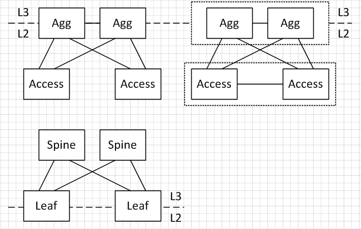
The topologies for option 1 and 2 are considered to be Aggregation-Access type topologies rather than Clos based spine-leaf topologies.
In the top left diagram (RSTP) we have all IEEE 802.1Q trunks carrying all VLANs. For any given VLAN the STP root bridge is placed at the Aggregation layer e.g., the left hand aggregation router, resulting in the access layer switch interface connecting to the right hand aggregation router being in the spanning tree blocking state. The topology uses a very standard design and is well understood.
In the top right diagram we use Cisco virtual Port Channel (vPC). As before all VLANs are carried on all trunks, but as they're now using IEEE 802.3ad Link Aggregation, there's a single logical link between aggregation and access and so no links are blocking. The only change from a physical perspective is the introduction of the link between an access switch pair that is used for the vPC peer link.
The bottom topology is what is commonly referred to as a spine-leaf topology. In this model there are no connections between any of the spines. All leaf switches connect to all spine switches, but there are no connections between leaf switches except for supporting Cisco vPC that I mentioned previously.
These would be my preferred topologies for each of the three options, which is generally some form of adaptation on your design A. As I mentioned above, I've only ever used your option B once, and that was for a very specific use case.
Regards
- Mark as New
- Bookmark
- Subscribe
- Mute
- Subscribe to RSS Feed
- Permalink
- Report Inappropriate Content
08-14-2015 12:03 AM
Hi,
As I described above, the U model is one where a VLAN would be configured on the aggregation routers, access switches and trunks between them, but would not be allowed on the trunk between the aggregation.
Assume we have VLAN 10 and 11 created on the aggregation routers, and then we create VLAN 10 on Acc1/Acc2 and allowed on the blue links, and create VLAN 11 on Acc3/Acc4 and allowed on the gold links. Neither VLAN 10 or 11 is allowed on the red link.
In this example we would have no loops at Layer-2 so spanning tree does not block any links.
If we need to extend a VLAN beyong a pair of access switches, let's say we want to add VLAN 10 to Acc3 and Acc4, then this is where loops are introduced.
In this case the gold links in the above now become blue as well so we have a "figure 8" loop from Agg1-> Acc1 -> Acc2 -> Agg2 -> Agg4 -> Agg3 and back to Agg1.

So now we need spanning tree to block one of the links again, so lose the benefit we tried to get from the U model in the first place.
In top right (in your post ) why there is a connection between access switch ?
The three diagrams were reprenting the three technology/feature options that I see you have when using the Nexus 9000, those being spanning tree, vPC and spine-leaf with VXLAN. The top right diagram was showing the physical connections you might have when using Nexus vPC. When using vPC there is a concept called the "vPC peer link" that is needed between the two devices that form the vPC domain, and the link between the access switches was the vPC peer link.
Regards
- Mark as New
- Bookmark
- Subscribe
- Mute
- Subscribe to RSS Feed
- Permalink
- Report Inappropriate Content
08-05-2015 05:56 AM
In a typical Spine / Leaf topology the Leaf switches only have uplinks to the Spine, not to each other as well. Therefore I would stick with Option A.
- Mark as New
- Bookmark
- Subscribe
- Mute
- Subscribe to RSS Feed
- Permalink
- Report Inappropriate Content
08-06-2015 02:08 AM
Hi,
I'd agree with Sean in that a Clos network i.e., leaf-spine, are not built with connections between the leaf switches. In fact if you use the Nexus 9000 in ACI mode then connections between leaf switches are automatically disabled.
You don't say how you intend to use the Nexus 9000, but the exception to this would be if you're using Nexus 9000 in NX-OS mode with VXLAN and virtual Port Channel (vPC).
In this configuration there would be connectivity between the pair of leaf switches that are forming a vPC domain. There are details in the Building Redundant vPC VTEPs with Cisco Nexus 9300 Platform Switches and Virtual Port-Channel VTEP in MP-BGP EVPN VXLAN.
Regards
- Mark as New
- Bookmark
- Subscribe
- Mute
- Subscribe to RSS Feed
- Permalink
- Report Inappropriate Content
08-08-2015 01:18 AM
Hi ,
if i have vmware host and from the host one link goes to the one of the leaf and the other connection goes to the second leaf , in that case B would we better ? .
Thanks
- Mark as New
- Bookmark
- Subscribe
- Mute
- Subscribe to RSS Feed
- Permalink
- Report Inappropriate Content
08-08-2015 03:20 AM
Hi,
What you describe is a pretty standard model for a server with NIC teaming i.e., connecting across a pair of switches for resilience, but I don't see what the traffic flow would be such that your design B would be a better option.
I'm assuming the option B you show is what is sometimes referred to as the U design. So the two left hand leaf switches form a pair, and the two right hand leaf switches form another pair. In the case of your VMware server you'd have one NIC connecting to the upper left leaf switch, and the second NIC connecting to the lower left leaf switch.
The only time I've used this design is when we were connecting switches from different vendors and had incompatible spanning tree implementations. This meant we wanted to remove spanning tree completely and did so by not having any loops. The problem with the approach is one of scale in that as soon as you go beyond a single pair of switches carrying the same VLAN, you introduce a "figure 8" loop, and so spanning tree is again required.
Beyond the physical topology I think we need to understand other aspects of what you're considering and that will help understand which topology is the correct one.
Aside from the physical connectivity, we need to consider the Layer-2 technologies that are supported on the Nexus 9000 series platforms. To have a server using NIC teaming connected across multiple leaf switches you need to present the same VLAN to multiple switches. Doing so obviously introduces Layer-2 loops and so needs some mechanism to break those.
As I see it with the Nexus 9000 you basically have three options:
- IEEE 802.1Q trunks using Rapid Spanning Tree to break Layer-2 loops
- IEEE 802.1Q trunks using Cisco virtual Port Channel to break Layer-2 loops
- Routed trunks (no L2 loops) and using VXLAN to extend L2 across the leaf switches
Option 1 has obviously been around for many years, but has inherent issues. For example broadcast storms if STP breaks, and STP logically blocking links meaning not all provisioned bandwidth is available.
Option 2 has been in widespread use for 5-6 years now and has the advantage over RSTP that there are no logically blocked links and so allows all provisioned bandwidth to be used all the time.
Both options 1 and 2 have issues if you are going to very large scale due to MAC scaling in the switches and the flooding behaviour of bridging.
This is where option 3 comes in. The advantage is that it allows Layer-2 across any number of switches, but does so in a much more scalable manner, especially when used with Multiprotocol BGP and L2 EVPN as the control plane. The downside of this approach is that it's much less mature than the other solutions.
So what would the physical topology look like for each of these? Generally they would connect as follows:
The topologies for option 1 and 2 are considered to be Aggregation-Access type topologies rather than Clos based spine-leaf topologies.
In the top left diagram (RSTP) we have all IEEE 802.1Q trunks carrying all VLANs. For any given VLAN the STP root bridge is placed at the Aggregation layer e.g., the left hand aggregation router, resulting in the access layer switch interface connecting to the right hand aggregation router being in the spanning tree blocking state. The topology uses a very standard design and is well understood.
In the top right diagram we use Cisco virtual Port Channel (vPC). As before all VLANs are carried on all trunks, but as they're now using IEEE 802.3ad Link Aggregation, there's a single logical link between aggregation and access and so no links are blocking. The only change from a physical perspective is the introduction of the link between an access switch pair that is used for the vPC peer link.
The bottom topology is what is commonly referred to as a spine-leaf topology. In this model there are no connections between any of the spines. All leaf switches connect to all spine switches, but there are no connections between leaf switches except for supporting Cisco vPC that I mentioned previously.
These would be my preferred topologies for each of the three options, which is generally some form of adaptation on your design A. As I mentioned above, I've only ever used your option B once, and that was for a very specific use case.
Regards
- Mark as New
- Bookmark
- Subscribe
- Mute
- Subscribe to RSS Feed
- Permalink
- Report Inappropriate Content
08-12-2015 09:07 PM
Hi ,
1 . " The problem with the approach is one of scale in that as soon as you go beyond a single pair of switches carrying the same VLAN, you introduce a "figure 8" loop, and so spanning tree is again required."
it would be great if you give me an example .
In top right (in your post ) why there is a connection between access switch ?
Thanks
- Mark as New
- Bookmark
- Subscribe
- Mute
- Subscribe to RSS Feed
- Permalink
- Report Inappropriate Content
08-14-2015 12:03 AM
Hi,
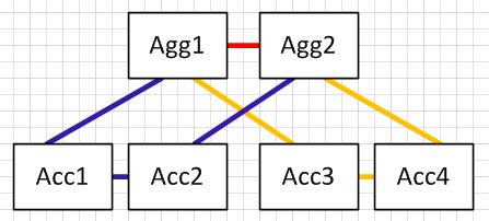
As I described above, the U model is one where a VLAN would be configured on the aggregation routers, access switches and trunks between them, but would not be allowed on the trunk between the aggregation.
Assume we have VLAN 10 and 11 created on the aggregation routers, and then we create VLAN 10 on Acc1/Acc2 and allowed on the blue links, and create VLAN 11 on Acc3/Acc4 and allowed on the gold links. Neither VLAN 10 or 11 is allowed on the red link.
In this example we would have no loops at Layer-2 so spanning tree does not block any links.
If we need to extend a VLAN beyong a pair of access switches, let's say we want to add VLAN 10 to Acc3 and Acc4, then this is where loops are introduced.
In this case the gold links in the above now become blue as well so we have a "figure 8" loop from Agg1-> Acc1 -> Acc2 -> Agg2 -> Agg4 -> Agg3 and back to Agg1.
So now we need spanning tree to block one of the links again, so lose the benefit we tried to get from the U model in the first place.
In top right (in your post ) why there is a connection between access switch ?
The three diagrams were reprenting the three technology/feature options that I see you have when using the Nexus 9000, those being spanning tree, vPC and spine-leaf with VXLAN. The top right diagram was showing the physical connections you might have when using Nexus vPC. When using vPC there is a concept called the "vPC peer link" that is needed between the two devices that form the vPC domain, and the link between the access switches was the vPC peer link.
Regards
- Mark as New
- Bookmark
- Subscribe
- Mute
- Subscribe to RSS Feed
- Permalink
- Report Inappropriate Content
08-17-2015 11:25 AM
Hi ,
Thanks for detailed explanation .
I just try to elaborate second option you posted earlier (Top right Diagram )
i have attached the diagram .Please post your valuable feedback .
Secondly .
In spine and leaf configuration (3rd) , for example a server in vlan 10 connected to left leaf and another server in the same vlan in the right leaf . How would be the traffic flow
In second option ( top right diagram )
a server in vlan 10 connected to left access switch and another server in the same vlan in the right access switch . How would be the traffic flow .
Basically my question is what are the advantages spine - leaf configuration have when comparing vpc( option 2 )
Thanks
- Mark as New
- Bookmark
- Subscribe
- Mute
- Subscribe to RSS Feed
- Permalink
- Report Inappropriate Content
08-19-2015 01:04 AM
Hi,
i have attached the diagram .Please post your valuable feedback .
The diagram you show is a standard topology for vPC, albeit drawn a little differently, so would work perfectly well. Remember you also need a vPC peer keepalive link for the vPC domains on the access switches. There are plenty of design guides for vPC on the Cisco web site including the Design and Configuration Guide: Best Practices for Virtual Port Channels (vPC) on Cisco Nexus 7000 Series Switches and the Quick Start Guide :: Virtual Port Channel (vPC).
In spine and leaf configuration (3rd) , for example a server in vlan 10 connected to left leaf and another server in the same vlan in the right leaf . How would be the traffic flow
A frame from the server on the left leaf would be received by the switch on the edge port. That entire frame would be encapsulated within a VXLAN packet, that packet having a source IP address of the left leaf VTEP interface and a destination IP address of the right leaf VTEP interface. This packet would be forwarded using the next hop learned via routing established to advertised the VTEP IP addresses i.e., an IGP for the underlay network, and would route via one of the spines switches to the right leaf. The right leaf switch would decapsulate the frame and forward to the destination server.
a server in vlan 10 connected to left access switch and another server in the same vlan in the right access switch . How would be the traffic flow .
This is going to use standard IEEE 802.1Q bridging and so would take the path with the lowest cost, which is likely to be the vPC peer link. Assuming you would have spanning-tree pathcost method long configured, with two 10 Gigabit Ethernet links for the vPC peer link, the cost of that link would be 1000. To have a path via the aggregation layer with a lower cost you'd need more than four 10 Gigabit Ethernet links such that cost of the path up and back down was lower than 1000.
There are details of the spanning tree cost in the Pathcost Method long section of the Spanning Tree Design Guidelines for Cisco NX-OS Software and Virtual PortChannels design guide.
Basically my question is what are the advantages spine - leaf configuration have when comparing vpc( option 2 )
As I mentioned previously, the advantage is that it provides Layer-2 across any number of switches, but does so in a much more scalable manner. Leaf and spine is a physical topology so doesn't offer any real advantage. The advantage comes when combining the physical leaf-spine topology with VXLAN, Ethernet VPN and Multiprotocol BGP. Some of the advantages listed in the EVPN design guide I mentioned previously are:
- The MP-BGP EVPN protocol is based on industry standards, allowing multivendor interoperability.
- It enables control-plane learning of end-host Layer-2 and Layer-3 reachability information, enabling organizations to build more robust and scalable VXLAN overlay networks.
- It uses the decade-old MP-BGP VPN technology to support scalable multitenant VXLAN overlay networks.
- The EVPN address family carries both Layer-2 and Layer-3 reachability information, thus providing integrated bridging and routing in VXLAN overlay networks.
- It minimizes network flooding through protocol-based host MAC/IP route distribution and Address Resolution Protocol (ARP) suppression on the local VTEPs.
- It provides optimal forwarding for east-west and north-south traffic and supports workload mobility with the distributed anycast function.
Regards
- Mark as New
- Bookmark
- Subscribe
- Mute
- Subscribe to RSS Feed
- Permalink
- Report Inappropriate Content
10-20-2015 05:30 AM
Hi Steve ,
for spine and leaf configuration , does it mandatory to have APIC controllers
Thanks
- Mark as New
- Bookmark
- Subscribe
- Mute
- Subscribe to RSS Feed
- Permalink
- Report Inappropriate Content
10-20-2015 06:36 AM
Hi,
If you use the Nexus 9000 in Cisco Application Centric Infrastructure (ACI) mode then you must also use the Cisco Application Policy Infrastructure Controller. If you intend to use the Nexus 9000 in NX-OS “stand alone” mode then Cisco APIC is not required.
As explained above, a “leaf-spine” network is a physical topology and is not related to the Cisco ACI solution or APIC that is part of that solution. The fact that the Cisco ACI is built in a leaf-spine topology is irrelevant.
Note that there is a specific Application Centric Infrastructure forum, and if you have specific questions related to ACI or APIC, that would be best place to post them.
Regards
- Mark as New
- Bookmark
- Subscribe
- Mute
- Subscribe to RSS Feed
- Permalink
- Report Inappropriate Content
10-20-2015 08:43 AM
Hi ,
Thank you so much . Just one more question .
You said "The fact that the Cisco ACI is built in a leaf-spine topology is irrelevant."
Can you tell me why you said so ?
Thanks
- Mark as New
- Bookmark
- Subscribe
- Mute
- Subscribe to RSS Feed
- Permalink
- Report Inappropriate Content
10-20-2015 09:10 AM
I said that from the point of view that a leaf-spine topology and Cisco ACI are two totally separate things.
A leaf-spine network is a physical topology, and I could build that topology with other Cisco switches e.g., Nexus 7000 and Nexus 5600. Equally I could build that topology with Arista switches, or Brocade, Dell, HP etc.
Having a leaf-spine network does not mean that I have to have Cisco ACI.
Regards
- Mark as New
- Bookmark
- Subscribe
- Mute
- Subscribe to RSS Feed
- Permalink
- Report Inappropriate Content
10-20-2015 04:52 PM
Hi Steve
When I read your posts it make me realise just how very average mine are.
Great posts in this thread and I will be going through them in some detail.
One very basic question with the physical topology diagrams you posted.
On the vPC topology there is a physical link between the access switches which confused me a little .
Is this because it is a double sided vPC or whatever the term for it is and that is why you need a vPC peer link between the access switches ?
Or am I way off the mark ?
Jon
- Mark as New
- Bookmark
- Subscribe
- Mute
- Subscribe to RSS Feed
- Permalink
- Report Inappropriate Content
10-20-2015 10:24 PM
Hi Jon,
Thanks for the comment. Very much appreciated.
And your posts are not average. You don't answer as many questions and solve as many problems as you do with average posts.
Back to the matter in hand.... you're spot on about the links between the access layer switches. It is the vPC peer link for the vPC domain that is configured on the access layer. In that scenario we have a vPC domain configured at the aggregation/distribution layer and then a second independent vPC domain configured on the access layer switches. We then build a single port-channel between all four switches, and hence the term "double sided" vPC.
Regards
Discover and save your favorite ideas. Come back to expert answers, step-by-step guides, recent topics, and more.
New here? Get started with these tips. How to use Community New member guide
