- Cisco Community
- Technology and Support
- Networking
- Switching
- Q: Vlans on layer 2
- Subscribe to RSS Feed
- Mark Topic as New
- Mark Topic as Read
- Float this Topic for Current User
- Bookmark
- Subscribe
- Mute
- Printer Friendly Page
Q: Vlans on layer 2
- Mark as New
- Bookmark
- Subscribe
- Mute
- Subscribe to RSS Feed
- Permalink
- Report Inappropriate Content
08-22-2019 08:42 PM
Hi all,
My experience is not great in the field of Cisco, because I have been working on Microsoft networks for a long time.
But I have a question now I download 7.2.1.0218, and I drew the attached diagram and created a number of vlans also I put a computer on each switch and take automatic IP.
But the problem is that the computer devices do not read each other and are not ping for switches.
I know that the switches in the diagram are from the Layer 2, but on the program does not accept the "ip route 0.0.0.0 0.0.0.0 xxxx" command, also the existing router as shown in the diagram is a normal router, not a Cisco router to configure routing.
Is there a solution to this problem and that the devices and switches can read each other on this situation, and if there is a need to change the switch is possible to change the first switch only "Main"
Thanks for your support and I'm a waiting your reply
- Labels:
-
LAN Switching
- Mark as New
- Bookmark
- Subscribe
- Mute
- Subscribe to RSS Feed
- Permalink
- Report Inappropriate Content
08-22-2019 10:01 PM - edited 08-22-2019 10:04 PM
L2 switch works at layer 2 with mac addresses and vlans, but does not do any routing. L3 sw and routers do routing.
L2 devices do not accept ip route 0.0.0.0 0.0.0.0; only L3 switches and routers.
L2 switch should have 1 IP on interface Vlan x and ip default-gateway x.x.x.x (of a router). All PCs' default gateway should be a router; not L2 switch.
you can replace L2 sw with L3 sw but then PCs default gateway should be that L3 sw.
Regards, ML
**Please Rate All Helpful Responses **
- Mark as New
- Bookmark
- Subscribe
- Mute
- Subscribe to RSS Feed
- Permalink
- Report Inappropriate Content
08-23-2019 03:13 AM
@Martin L wrote:Regards, ML
**Please Rate All Helpful Responses **
Thanks Martin for reply need change all SW or main switch, and you can give me example like I attached at first topic by layer 3
Thanks
- Mark as New
- Bookmark
- Subscribe
- Mute
- Subscribe to RSS Feed
- Permalink
- Report Inappropriate Content
08-23-2019 07:34 AM - edited 08-23-2019 08:06 AM
the main one; in your topology, the main sw should be L3 with a router playing role of ISP connector, WAN router.
L3 can have following (just example)
interface vlan 100
ip address 10.0.3.1 255.255.255.0
interface vl 200
ip address 10.0.2.1 255.255.255.0
interface vlan 300
ip address 10.0.4.1 /24
etc
you still need a trunks from L3 to L2 switches and one interface vlan x going to router. you can then enable ip routing on L3 switch and add protocol or static route. ip default gateway 0.0.0.00/0 should be pointing to router.
There are samples in PT; i think u should be able to find couple of them where switches are L3 and l2.
Regards, ML
**Please Rate All Helpful Responses **
- Mark as New
- Bookmark
- Subscribe
- Mute
- Subscribe to RSS Feed
- Permalink
- Report Inappropriate Content
08-24-2019 09:31 AM
I updated and add new designed scheme of 2 L3 switches. I think called collapsed backbone design.
get PT file from https://learningnetwork.cisco.com/docs/DOC-36982
- Mark as New
- Bookmark
- Subscribe
- Mute
- Subscribe to RSS Feed
- Permalink
- Report Inappropriate Content
08-24-2019 11:02 AM
@Martin L wrote:
I updated and add new designed scheme of 2 L3 switches. I think called collapsed backbone design.
get PT file from https://learningnetwork.cisco.com/docs/DOC-36982
Thanks Martin
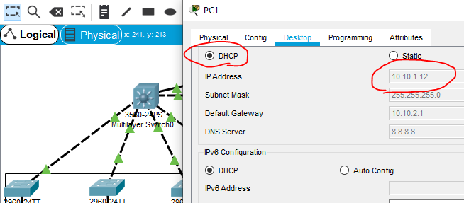
But also not ping from PC to other "attached", also I need ask why when I press DHCP in any SW L2 get different IP from any Vlan "attached"
- Mark as New
- Bookmark
- Subscribe
- Mute
- Subscribe to RSS Feed
- Permalink
- Report Inappropriate Content
08-24-2019 01:23 PM - edited 08-24-2019 01:32 PM
I think I see Default gateway on PC is not on the same network / subnet as IP of PCs.
i.e
ip 10,10,1,12 /24
default gateway 10.10.1.1
u can attach your work if u want , pt file
Regards, ML
**Please Rate All Helpful Responses **
Discover and save your favorite ideas. Come back to expert answers, step-by-step guides, recent topics, and more.
New here? Get started with these tips. How to use Community New member guide