- Cisco Community
- シスコ コミュニティ
- ネットワークインフラストラクチャ
- [TKB] ネットワークインフラ ドキュメント
- NAT Box to Box High Availabitliy 機能の概要
- RSS フィードを購読する
- 新着としてマーク
- 既読としてマーク
- ブックマーク
- 購読
- 印刷用ページ
- 不適切なコンテンツを報告
- RSS フィードを購読する
- 新着としてマーク
- 既読としてマーク
- ブックマーク
- 購読
- 印刷用ページ
- 不適切なコンテンツを報告
2014-01-08 08:47 PM 2019-03-22 07:04 AM 更新
本記事では ISRG2 Router における NAT Box to Box High Availability 機能の概要を説明します。
本機能のバックグラウンド
これまで、Dynamic NAT を使用する Router の冗長化機能として、IOS では Stateful NAT 機能がありましたが、
15.0M 以降の IOS Version では Stateful NAT 機能は非サポートとなっております。
さらに Stateful NAT 機能自体も January 31, 2014 をもって End of Support となり、TAC でのサポートが終了いたします。
End-of-Sale and End-of-Life Announcement for the Cisco IOS Stateful Failover of Network Address Translation (SNAT)
上記ではStateful NAT の代替機能として Cisco ASA Adaptive Security Appliance high availability が紹介されております。
その後、IOS 15.3(2)T 以降にて新たに NAT Box-to-Box High-Availability という機能が追加され、
この機能を用いることで、ISR G2 Router でも Stateful NAT と同様の冗長性を実現することが可能となります。
以下では NAT Box-to-Box High-Availability の概要、基本構成・設定、Troubleshooting に必要なログについて説明します。
return to top1. 機能概要
NAT Box to Box High Availabitliy 機能(以下、NAT BtoB HA)は、NAT router における link や Router の予期せぬ問題への耐障害性を高める機能となります。
また Dynamic NAT での非対称ルーティング (asymmetric routing) もサポートされます。
NAT BtoB HA 機能は、Active-Standby を制御する Redundancy Group (RG) と呼ばれる機能と
Network Address Translation (NAT) 機能の2つの構成要素からなります。
このため、NAT BtoB HA では RG/NAT の2つの構成要素について設定を行います。
現状では ALG が FTP application のみでサポートされる、等の制約事項もあるため、
導入に際しては以下などを参照の上、十分検証いただけますようお願いします。
Restrictions for NAT Box-to-Box High-Availability Support
現在 NAT BtoB HA でサポートされている NAT 機能は以下となります。
Interface overload options はサポートされていないため、ご注意ください。
-Simple Static NAT configuration
-Extended Static NAT configuration
-Network Static NAT configuration
-Dynamic NAT and Port Address Translation (PAT) configuration
-NAT inside source, outside source, and inside destination rules
-NAT rules for Virtual Routing and Forwarding (VRF) instances to IP
-NAT rules for VRF-VRF (within same VRF)
return to top2. 基本構成
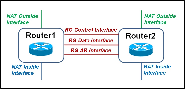
NAT BtoB HA では以下の interface を定義する必要があります。
Figure. 1 に構成の概念的図を示します。
-NAT inside/outside interface
-RG control interface (RGにて管理情報のやり取りに使用)
-RG data interface (NAT session情報などのやり取りに使用)
-RG Asymmetric Routing (AR) interface (AR packetを Standby から Activeへの転送に使用, optional)
なお、RG Control/Data/AR interface を同一の物理 Interface に定義することも可能です。
Figure. 1

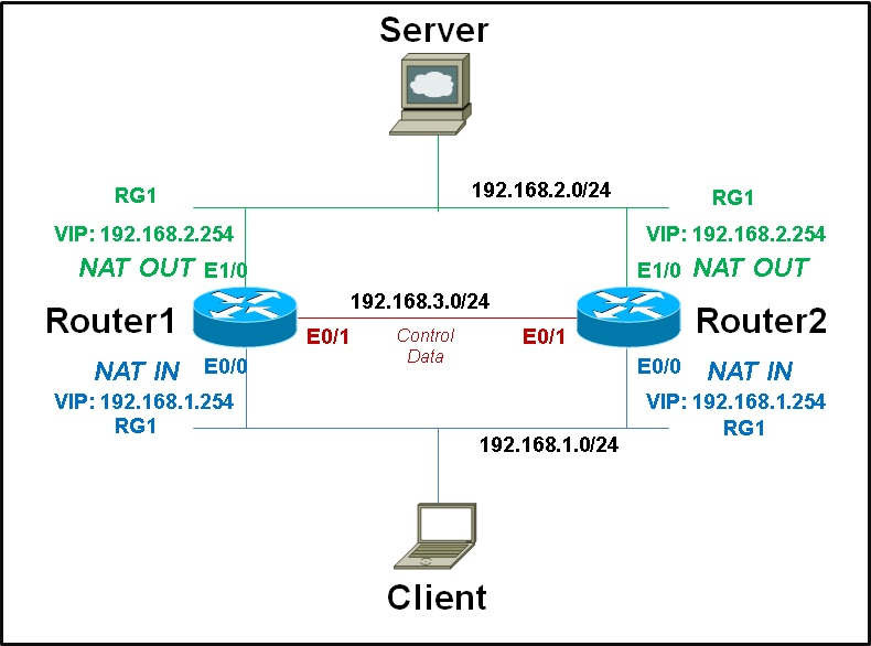
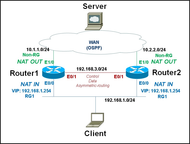
NAT BtoB HA では NAT inside/outside の両側を冗長させる(LAN-LAN)構成と、inside側のみを冗長させる(WAN-LAN)構成が実現可能です。それぞれ、Figure. 2 のような構成イメージとなります。
Figure. 2

3. 基本設定
以下では LAN-LAN と WAN-LAN のそれぞれの構成について、設定例を紹介します。
LAN-LAN 構成の設定例
ここでは Figure. 3 に示す構成を想定した設定例となります。
Stateful NAT とは異なり、HSRP の設定(standby ip コマンド等)は不要な点にもご注意ください。
Figure. 3

/// Router1 ///
redundancy

application redundancy

  group 1

   name RG1

   preempt

   priority 105

   control Ethernet0/1 protocol 1

   data Ethernet0/1


interface Ethernet0/0

ip address 192.168.1.1 255.255.255.0

ip nat inside

ip virtual-reassembly in

redundancy rii 100

redundancy group 1 ip 192.168.1.254 exclusive decrement 100


interface Ethernet0/1

ip address 192.168.3.1 255.255.255.0


interface Ethernet1/0

ip address 192.168.2.1 255.255.255.0

ip nat outside

ip virtual-reassembly in

redundancy rii 101

redundancy group 1 ip 192.168.2.254 exclusive decrement 100


ip nat inside source static 192.168.1.3 192.168.2.3 redundancy 1 mapping-id 120
/// Router2 ///
redundancy

application redundancy

  group 1

   name RG1

   preempt

   control Ethernet0/1 protocol 1

   data Ethernet0/1


interface Ethernet0/0

ip address 192.168.1.2 255.255.255.0

ip nat inside

ip virtual-reassembly in

redundancy rii 100

redundancy group 1 ip 192.168.1.254 exclusive decrement 100


interface Ethernet0/1

ip address 192.168.3.2 255.255.255.0


interface Ethernet1/0

ip address 192.168.2.2 255.255.255.0

ip nat outside

ip virtual-reassembly in

redundancy rii 101

redundancy group 1 ip 192.168.2.254 exclusive decrement 100


ip nat inside source static 192.168.1.3 192.168.2.3 redundancy 1 mapping-id 120
WAN-LAN 構成の設定例
ここではFigure. 4に示す構成を想定した設定例となります。
また以下の機能設定も行っておりますが必須ではありません。
-RG Aymmetric-routing を使用 (*1)
-WAN側のRouting Protocol にOSPFを使用 (*2)
-Virtual IP (VIP) が Routing table にある場合のみ WAN側 Routing Protocol (OSPF) に再配送されるよう Track の設定を使用 (*3)
Figure. 4

/// Router1 ///
redundancy

application redundancy

  group 1

   name RG1

   preempt

   priority 105

   control Ethernet0/1 protocol 1

   data Ethernet0/1

   asymmetric-routing interface Ethernet0/1     (*1)

track 100 ip route 192.168.1.254 255.255.255.255 reachability     (*3)

interface Ethernet0/0

ip address 192.168.1.1 255.255.255.0

ip nat inside

ip virtual-reassembly in

redundancy rii 100

redundancy group 1 ip 192.168.1.254 exclusive decrement 100


interface Ethernet0/1

ip address 192.168.3.1 255.255.255.0


interface Ethernet1/0

ip address 10.1.1.1 255.255.255.0

ip nat outside

ip virtual-reassembly in

redundancy rii 101

redundancy asymmetric-routing enable     (*1)


router ospf 1     (*2)

router-id 10.1.1.1

redistribute static subnets

network 10.0.0.0 0.255.255.255 area 0

ip nat inside source static 192.168.1.3 10.10.10.10 redundancy 1 mapping-id 120


ip route 10.10.10.10 255.255.255.255 Ethernet0/0 track 100     (*3)
/// Router2 ///
redundancy

application redundancy

  group 1

   name RG1

   preempt

   control Ethernet0/1 protocol 1

   data Ethernet0/1

   asymmetric-routing interface Ethernet0/1     (*1)


track 100 ip route 192.168.1.254 255.255.255.255 reachability     (*3)


interface Ethernet0/0

ip address 192.168.1.2 255.255.255.0

ip nat inside

ip virtual-reassembly in

redundancy rii 100

redundancy group 1 ip 192.168.1.254 exclusive decrement 100


interface Ethernet0/1

ip address 192.168.3.2 255.255.255.0


interface Ethernet1/0

ip address 10.2.2.2 255.255.255.0

ip nat outside

ip virtual-reassembly in

redundancy rii 101

redundancy asymmetric-routing enable     (*1)


router ospf 1     (*2)

router-id 10.2.2.1

redistribute static subnets

network 10.0.0.0 0.255.255.255 area 0


ip nat inside source static 192.168.1.3 10.10.10.10 redundancy 1 mapping-id 120


ip route 10.10.10.10 255.255.255.255 Ethernet0/0 track 100     (*3)
return to top
4. TAC調査に当たり取得いただきたいログ
調査に当たり、まずは以下の情報などをご確認ください。
show ip nat redundancy <RG-id>
show ip nat translations redundancy <RG-id> [verbose]
show redundancy application group <RG-id>
show redundancy application protocol group <RG-id>
show ip route
show ip alias
show ip cef
show tech-support
商用環境でのdebug の取得は影響度に十分ご注意ください。
debug ip nat [detailed]
debug ip nat redundancy errors
debug ip nat redundancy messages [[detailed] [errors ]]
debug ip nat redundancy packets
debug ip nat redundancy db [errors]
debug ip nat redundancy cf
debug ip nat redundancy rf [errors]
(補足)特定のRGグループのセッションをクリアするには以下のコマンドを実行してください。
clear ip nat translation redundancy <RG-id> *
clear ip nat translation redundancy <RG-id> forced
上記で紹介した設定コマンドなどの詳細は以下の Cisco.com ページをご参照ください。
IP Addressing: NAT Configuration Guide, Cisco IOS Release 15M&T
NAT Box-to-Box High-Availability Support
http://www.cisco.com/en/US/docs/ios-xml/ios/ipaddr_nat/configuration/15-mt/iadnat-b2b-ha.htm
return to top検索バーにキーワード、フレーズ、または質問を入力し、お探しのものを見つけましょう
シスコ コミュニティをいち早く使いこなしていただけるよう役立つリンクをまとめました。みなさんのジャーニーがより良いものとなるようお手伝いします
下記より関連するコンテンツにアクセスできます


