- Cisco Community
- Technology and Support
- Wireless - Mobility
- Wireless - Mobility Knowledge Base
- Getting started with Unified Access WLC 5760 and Catalyst 3850
- Subscribe to RSS Feed
- Mark as New
- Mark as Read
- Bookmark
- Subscribe
- Printer Friendly Page
- Report Inappropriate Content
- Subscribe to RSS Feed
- Mark as New
- Mark as Read
- Bookmark
- Subscribe
- Printer Friendly Page
- Report Inappropriate Content
06-25-2013 05:18 AM - edited 11-18-2020 03:03 AM
- Introduction
- Overview of the Unified Access CT5760 Wireless Controller
- Overview of the Unified Access Catalyst 3850 Switches
- Initial configuration of the 5760 WLC
- Initial configuration of the 3850 Switch
Introduction
This document describes the steps needed to successfully install and get the WLC 5760 and Switch 3850 operational and ready to host Wireless Access Points, WLANs and Wireless clients.
This document only covers initial configuration on both of the platforms.
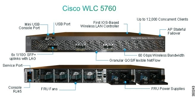
Overview of the Unified Access CT5760 Wireless Controller
The CT5760 Wireless LAN Controller (WLC) is the first Cisco IOS® software-based controller built with smart ASIC intended to be deployed as a centralized controller in the next generation unified wireless architecture. CT5760 controllers are specifically designed to function like the older unified model central wireless controllers. They also support the newer Mobility functionality with Next Generation Wireless Controllers 3850 switches in the wireless architecture.
CT5760 controllers are deployed behind a core switch/router. The core switch/router is the only gateway into the network for the controller. The uplink ports connected to the core switch are configured as EtherChannel trunk to ensure port redundancy.
This new controller is an extensible and high performance wireless controller, which can scale up to 1000 access points (AP) and 12,000 clients. The controller has eight 6-10 Gbps data ports.
As a component of the Cisco Unified Wireless Network, the 5760 series works in conjunction with Cisco Aironet Access Points, the Cisco Prime Infrastructure, and the Cisco Mobility Services Engine to support business-critical wireless data, voice, and video applications.
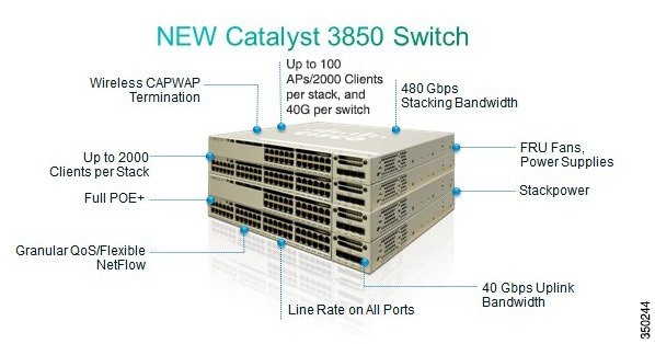
Overview of the Unified Access Catalyst 3850 Switches
The Unified Access Catalyst 3850 switch is a flexible ASIC-based hardware that can support multiple protocols and has many advantages over the current hardware platform. The Catalyst 3850 switch has an integrated hardware-based wireless support with Control and Provisioning of Wireless Access Points (CAPWAP) and fragmentation. It also has 40 GB of uplink bandwidth when all ports function at line rate.
The Catalyst 3850 switch provides an open service platform. It has a 4-core CPU to leverage the operating system (OS) and to host various services. The Catalyst 3850 hardware is the next- generation switching hardware.
The UA Catalyst 3850 switch has unified wired and wireless architecture. The wireless operating system is Cisco IOS® software-based. UA Catalyst 3850 switch provides uniform wired and wireless policies. It can house 50 access points (802.11n) and support 2000 clients per stack.
Initial configuration of the 5760 WLC
Here are the steps needed to successfully configure your 5760 WLC to start hosting wireless services.
Version used : 03.02.02
Setup Script
         --- System Configuration Dialog ---

Enable secret warning
----------------------------------
In order to access the device manager, an enable secret is required
If you enter the initial configuration dialog, you will be prompted for the enable secret
If you choose not to enter the inital configuration dialog, or if you exit setup without setting the enable secret,
please set an enable secret using the following CLI in configuration mode-
enable secret 0 <cleartext password>
----------------------------------

Would you like to enter the initial configuration dialog? [yes/no]: yes

At any point you may enter a question mark '?' for help.
Use ctrl-c to abort configuration dialog at any prompt.
Default settings are in square brackets '[]'.

Basic management setup configures only enough connectivity

for management of the system, extended setup will ask you
to configure each interface on the system

Would you like to enter basic management setup? [yes/no]: yes

Configuring global parameters:

  Enter host name [Controller]: w-5760-1

  The enable secret is a password used to protect access to
  privileged EXEC and configuration modes. This password, after
  entered, becomes encrypted in the configuration.
  Enter enable secret: cisco

  The enable password is used when you do not specify an
  enable secret password, with some older software versions, and
  some boot images.
  Enter enable password: cisco

  The virtual terminal password is used to protect
  access to the router over a network interface.
  Enter virtual terminal password: cisco

Configure a NTP server now? [yes]:
Enter ntp server address : 192.168.1.200
Enter a polling interval between 16 and 131072 secs which is power of 2:16

  Do you want to configure wireless network? [no]:

Setup account for accessing HTTP server? [yes]:
    Username  [admin]:
    Password  [cisco]:
    Password is UNENCRYPTED.

  Configure SNMP Network Management? [no]:

Current interface summary

Any interface listed with OK? value "NO" does not have a valid configuration

Interface                        IP-Address      OK?  Method Status                Protocol

Vlan1                             unassigned      NO   unset     up                        up
GigabitEthernet0/0     unassigned      YES  unset     up                        up
Te1/0/1                          unassigned      YES  unset     up                        up
Te1/0/2                          unassigned      YES  unset     down                  down
Te1/0/3                          unassigned      YES  unset     down                  down
Te1/0/4                         unassigned      YES  unset      down                   down
Te1/0/5                         unassigned      YES  unset      down                   down
Te1/0/6                         unassigned      YES  unset      down                   down

Enter interface name used to connect to the
management network from the above interface summary: vlan1

Configuring interface Vlan1:

  Configure IP on this interface? [yes]:
    IP address for this interface: 192.168.1.20
    Subnet mask for this interface [255.255.255.0] :

    Class C network is 192.168.1.0, 24 subnet bits; mask is /24

Wireless management interface needs to be configured at startup
It needs to be mapped to an SVI that's not Vlan 1 (default)

Enter VLAN No for wireless management interface:  120

Enter IP address :192.168.120.94
Enter IP address mask:  255.255.255.0

The following configuration command script was created:

hostname w-5760-1
enable secret 4 tnhtc92DXBhelxjYk8LWJrPV36S2i4ntXrpb4RFmfqY^Q
enable password cisco
line vty 0 15
password cisco
ntp server 192.168.1.200 maxpoll 4 minpoll 4

username admin privilege 15 password cisco
no snmp-server
!
no ip routing


!
interface Vlan1
no shutdown
ip address 192.168.1.20 255.255.255.0
!
interface GigabitEthernet0/0
shutdown
no ip address
!
interface TenGigabitEthernet1/0/1
!
interface TenGigabitEthernet1/0/2
!
interface TenGigabitEthernet1/0/3
!
interface TenGigabitEthernet1/0/4
!
interface TenGigabitEthernet1/0/5
!
interface TenGigabitEthernet1/0/6
vlan 120
interface vlan 120
ip addr  192.168.120.94 255.255.255.0
exit
wireless management interface Vlan120
!
end

[0] Go to the IOS command prompt without saving this config.
[1] Return back to the setup without saving this config.
[2] Save this configuration to nvram and exit.

Enter your selection [2]: 2

Building configuration...
Compressed configuration from 2729 bytes to 1613 bytes[OK]
Use the enabled mode 'configure' command to modify this configuration.

Press RETURN to get started!
Required Wireless configuration for Access Points to be able to join
Important Note:
Ensure that your switch is having the right boot command under global configuration. Depending how you installed the software on the switch. If it has been extracted on the flash, then the following boot command is required:
w-5760-1(config)#boot system flash:packages.conf
Connectivity Configuration
connecting to the backbone network and on which your will have CAPWAP traffic
coming in/out. In this document the interface used is TenGigabitEthernet1/0/1. We are allowing on it Vlan1 nd Vlan 120
      interface TenGigabitEthernet1/0/1
      switchport trunk allowed vlan 1,120
      switchport mode trunk
      ip dhcp relay information trusted
     ip dhcp snooping trust

   Configure default route out:

    ip route 0.0.0.0 0.0.0.0 192.168.1.1
Configure Web Access
The GUI can be accessed via https://<ipaddress>/wireless
The logon credentials are already defined in the initial configuration dialog
username admin privilege 15 password 0 admin

Ensure wireless management interface is correctly configured
    wireless management interface Vlan120

     w-5760-1#sh run int vlan 120

     Building configuration...

    Current configuration : 62 bytes
    !
    interface Vlan120
    ip address 192.168.120.94 255.255.255.0
   end

  w-5760-1#sh ip int br
  Interface                                  IP-Address      OK?    Method   Status            Protocol
  Vlan1                                      192.168.1.20      YES    manual    up                   up
  Vlan120                                 192.168.120.94  YES    manual    up                   up
  GigabitEthernet0/0              unassigned        YES      unset     down              down
Te1/0/1                                    unassigned        YES      unset      up                   up
Te1/0/2                                    unassigned        YES      unset    down               down
Te1/0/3                                    unassigned        YES      unset    down               down
Te1/0/4                                    unassigned        YES      unset    down               down
Te1/0/5                                    unassigned        YES      unset    down               down
Te1/0/6                                    unassigned        YES      unset    down               down
Capwap2                                unassigned        YES      unset    up                    up

w-5760-1#
Ensure you have enabled license with the right ap count
Note: The 5760 does not have activated license levels, the image is already ipservices
Note: 5760 acting as MC can support up to 1000 APs
w-5760-1#license right-to-use activate apcount <count> slot 1 acceptEULA
Country code
Ensure you have configured the correct country code on your WLC in compliance with the regulatory domain of the
country the AP(s) will be servicing in and in compliance with the regulatory domain of the AP(s)
w-5760-1#show wireless country configured

Configured Country.............................: US  - United States
Configured Country Codes
    US  - United States : 802.11a Indoor,Outdoor/ 802.11b / 802.11g

w-5760-1(config)#ap dot11 24ghz shutdown

w-5760-1(config)#ap dot11 5ghz shutdown

w-5760-1(config)#ap country BE
Changing  country code could reset channel and RRM grouping configuration. If  running in RRM One-Time mode, reassign channels after this command.  Check customized APs for valid channel values after this command.
Are you sure you want to continue? (y/n)[y]: y
w-5760-1(config)#no ap dot11 24ghz shut
w-5760-1(config)#no ap dot11 5ghz shut
w-5760-1(config)#end
w-5760-1#wr
Building configuration...
Compressed configuration from 3564 bytes to 2064 bytes[OK]

w-5760-1#show wireless country configured

Configured Country.............................: BE  - Belgium
Configured Country Codes
    BE  - Belgium : 802.11a Indoor,Outdoor/ 802.11b / 802.11g
AP --------> WLC Connectivity
Ensure that your AP(s) on whatever VLAN, they are able to learn the IP address of the WLC ( 192.168.120..94 in this example)
via DHCP option 43, DNS, or any other discovery mechanism in CAPWAP.
Monitoring and Debugging
Ensure that your AP(s) have joined:
w-5760-1#show ap summary

Number of APs: 1

Global AP User Name: Not configured

Global AP Dot1x User Name: Not configured

AP Name                           AP Model  Ethernet MAC    Radio MAC       State
--------------------------------------------------------------------------------------

APa493.4cf3.232a                  1042N     a493.4cf3.232a  10bd.186d.9a40  Registered
Useful debugs for troubleshooting AP join issues
w-5760-1#debug capwap ap events

capwap/ap/events debugging is on

w-5760-1#debug capwap ap error

capwap/ap/error debugging is on

w-5760-1#debug dtls ap event
dtls/ap/event debugging is on
DHCP Snooping and Trust Configuration
It is recommended to use external DHCP server instead of internal DHCP server. DHCP snooping configuration is required on the controller for proper client join functionality. DHCP snooping must be enabled on each client VLAN including the override VLAN, if override is applied on the WLAN. The following example shows how to configure DHCP snooping.
Global DHCP Snooping Configuration:
ip dhcp snooping
ip dhcp snooping vlan 100, 200
Enable the bootp-broadcast command. This command is used by clients who send DHCP messages with broadcast addresses and the broadcast bit is set in the DHCP message.
ip dhcp snooping wireless bootp-broadcast enable
On the Interface:
Note If upstream is via a port channel, the trust configuration must be configured on the port channel interface as well.
interface TenGigabitEthernet1/0/1
description Connection to Core Switch
switchport trunk allowed vlan 100, 200
switchport mode trunk
ip dhcp relay information trusted
ip dhcp snooping trust
Note DHCP snooping must be configured on the Guest Anchor controller for guest access similar to the configuration above.
If you are using an ip-helper address on the interface, you must modify option 82 behavior:
On the DHCP Snooping Device
no ip dhcp snooping information option
OR
On the DHCP Relay Device (per interface)
ip dhcp relay information trusted
On the DHCP Relay Device (global configuration)
ip dhcp relay information trust-all
Initial configuration of the 3850 Switch
Here are the steps needed to successfully configure your 3850 Switch to start hosting wireless services.
Version used : 03.02.02
Setup script
    --- System Configuration Dialog ---

Enable secret warning
----------------------------------
In order to access the device manager, an enable secret is required
If you enter the initial configuration dialog, you will be prompted for the enable secret
If you choose not to enter the intial configuration dialog, or if you exit setup without setting the enable secret,
please set an enable secret using the following CLI in configuration mode-
enable secret 0 <cleartext password>
----------------------------------
Would you like to enter the initial configuration dialog? [yes/no]: yes

At any point you may enter a question mark '?' for help.
Use ctrl-c to abort configuration dialog at any prompt.
Default settings are in square brackets '[]'.


Basic management setup configures only enough connectivity
for management of the system, extended setup will ask you
to configure each interface on the system


Would you like to enter basic management setup? [yes/no]: yes
Configuring global parameters:


  Enter host name [Switch]: sw-3850-1


  The enable secret is a password used to protect access to
  privileged EXEC and configuration modes. This password, after
  entered, becomes encrypted in the configuration.
  Enter enable secret: Cisco123


  The enable password is used when you do not specify an
  enable secret password, with some older software versions, and
  some boot images.
  Enter enable password: Cisco123


  The virtual terminal password is used to protect
  access to the router over a network interface.
  Enter virtual terminal password: Cisco123


  Do you want to configure country code? [no]: yes


  Enter the country code[US]:BE


Note :  Enter the country code in which you are installing this 3850 Switch and the AP(s). If your country code is not


             recognized, enter one that is compliant with the regulatory domain of your own country


Setup account for accessing HTTP server? [yes]:
    Username  [admin]:
    Password  [cisco]:
    Password is UNENCRYPTED.


  Configure SNMP Network Management? [no]:
Current interface summary
Any interface listed with OK? value "NO" does not have a valid configuration
Interface                           IP-Address      OK? Method Status                Protocol
Vlan1                               unassigned      NO  unset      up                    down
GigabitEthernet0/0      unassigned      YES unset      up                    up
GigabitEthernet2/0/1   unassigned      YES unset  down                  down
GigabitEthernet2/0/2   unassigned      YES unset  down                  down
GigabitEthernet2/0/3   unassigned      YES unset  down                  down
GigabitEthernet2/0/4   unassigned      YES unset  down                  down
GigabitEthernet2/0/5   unassigned      YES unset  down                  down
GigabitEthernet2/0/6   unassigned      YES unset  down                  down
GigabitEthernet2/0/7   unassigned      YES unset  down                  down
GigabitEthernet2/0/8   unassigned      YES unset  down                  down
GigabitEthernet2/0/9   unassigned      YES unset  down                  down
GigabitEthernet2/0/10  unassigned      YES unset  down                  down
GigabitEthernet2/0/11  unassigned      YES unset  down                  down
GigabitEthernet2/0/12  unassigned      YES unset  down                  down
GigabitEthernet2/0/13  unassigned      YES unset  down                  down
GigabitEthernet2/0/14  unassigned      YES unset  down                  down
GigabitEthernet2/0/15  unassigned      YES unset  down                  down
GigabitEthernet2/0/16  unassigned      YES unset  down                  down
GigabitEthernet2/0/17  unassigned      YES unset  down                  down
GigabitEthernet2/0/18  unassigned      YES unset  down                  down
GigabitEthernet2/0/19  unassigned      YES unset  down                  down
GigabitEthernet2/0/20  unassigned      YES unset  down                  down
GigabitEthernet2/0/21  unassigned      YES unset  down                  down
GigabitEthernet2/0/22  unassigned      YES unset  down                  down
GigabitEthernet2/0/23  unassigned      YES unset  down                  down
GigabitEthernet2/0/24  unassigned      YES unset  down                  down
GigabitEthernet2/0/25  unassigned      YES unset  down                  down
GigabitEthernet2/0/26  unassigned      YES unset  down                  down
GigabitEthernet2/0/27  unassigned      YES unset  down                  down
GigabitEthernet2/0/28  unassigned      YES unset  down                  down
GigabitEthernet2/0/29  unassigned      YES unset  down                  down
GigabitEthernet2/0/30  unassigned      YES unset  down                  down
GigabitEthernet2/0/31  unassigned      YES unset  down                  down
GigabitEthernet2/0/32  unassigned      YES unset  down                  down
GigabitEthernet2/0/33  unassigned      YES unset  down                  down
GigabitEthernet2/0/34  unassigned      YES unset  down                  down
GigabitEthernet2/0/35  unassigned      YES unset  down                  down
GigabitEthernet2/0/36  unassigned      YES unset  down                  down
GigabitEthernet2/0/37  unassigned      YES unset  down                  down
GigabitEthernet2/0/38  unassigned      YES unset  down                  down
GigabitEthernet2/0/39  unassigned      YES unset  down                  down
GigabitEthernet2/0/40  unassigned      YES unset  down                  down
GigabitEthernet2/0/41  unassigned      YES unset  down                  down
GigabitEthernet2/0/42  unassigned      YES unset  down                  down
GigabitEthernet2/0/43  unassigned      YES unset  down                  down
GigabitEthernet2/0/44  unassigned      YES unset  down                  down
GigabitEthernet2/0/45  unassigned      YES unset  down                  down
GigabitEthernet2/0/46  unassigned      YES unset  down                  down
GigabitEthernet2/0/47  unassigned      YES unset  down                  down
GigabitEthernet2/0/48  unassigned      YES unset  up                       up
GigabitEthernet2/1/1    unassigned      YES unset  down                  down
GigabitEthernet2/1/2   unassigned      YES unset  down                  down
GigabitEthernet2/1/3   unassigned      YES unset  down                  down
GigabitEthernet2/1/4   unassigned      YES unset  down                  down
Te2/1/1                           unassigned      YES unset  down                  down
Te2/1/2                           unassigned      YES unset  down                  down
Te2/1/3                           unassigned      YES unset  down                  down
Te2/1/4                           unassigned      YES unset  down                  down


Enter interface name used to connect to the
management network from the above interface summary: vlan1


Configuring interface Vlan1:
  Configure IP on this interface? [yes]:
    IP address for this interface: 192.168.1.2
    Subnet mask for this interface [255.255.255.0] :
    Class C network is 192.168.1.0, 24 subnet bits; mask is /24
The following configuration command script was created:
hostname sw-3850-1
enable secret 4 vwcGVdcUZcRMCyxaH2U9Y/PTujsnQWPSbt.LFG8lhTw
enable password Cisco123
line vty 0 15
password Cisco123
  ap dot11 24ghz shutdown
  ap dot11 5ghz shutdown
  ap country BE
  no ap dot11 24ghz shutdown
  no ap dot11 5ghz shutdown

username admin privilege 15 password 0 cisco
no snmp-server
!
no ip routing


!
interface Vlan1
no shutdown
ip address 192.168.1.2 255.255.255.0
!
interface GigabitEthernet0/0
shutdown
no ip address
!
interface GigabitEthernet2/0/1
!
interface GigabitEthernet2/0/2
!
interface GigabitEthernet2/0/3
!
interface GigabitEthernet2/0/4
!
interface GigabitEthernet2/0/5
!
interface GigabitEthernet2/0/6
!
interface GigabitEthernet2/0/7
!
interface GigabitEthernet2/0/8
!
interface GigabitEthernet2/0/9
!
interface GigabitEthernet2/0/10
!
interface GigabitEthernet2/0/11
!
interface GigabitEthernet2/0/12
!
interface GigabitEthernet2/0/13
!
interface GigabitEthernet2/0/14
!
interface GigabitEthernet2/0/15
!
interface GigabitEthernet2/0/16
!
interface GigabitEthernet2/0/17
!
interface GigabitEthernet2/0/18
!
interface GigabitEthernet2/0/19
!
interface GigabitEthernet2/0/20
!
interface GigabitEthernet2/0/21
!
interface GigabitEthernet2/0/22
!
interface GigabitEthernet2/0/23
!
interface GigabitEthernet2/0/24
!
interface GigabitEthernet2/0/25
!
interface GigabitEthernet2/0/26
!
interface GigabitEthernet2/0/27
!
interface GigabitEthernet2/0/28
!
interface GigabitEthernet2/0/29
!
interface GigabitEthernet2/0/30
!
interface GigabitEthernet2/0/31
!
interface GigabitEthernet2/0/32
!
interface GigabitEthernet2/0/33
!
interface GigabitEthernet2/0/34
!
interface GigabitEthernet2/0/35
!
interface GigabitEthernet2/0/36
!
interface GigabitEthernet2/0/37
!
interface GigabitEthernet2/0/38
!
interface GigabitEthernet2/0/39
!
interface GigabitEthernet2/0/40
!
interface GigabitEthernet2/0/41
!
interface GigabitEthernet2/0/42
!
interface GigabitEthernet2/0/43
!
interface GigabitEthernet2/0/44
!
interface GigabitEthernet2/0/45
!
interface GigabitEthernet2/0/46
!
interface GigabitEthernet2/0/47
!
interface GigabitEthernet2/0/48
!
interface GigabitEthernet2/1/1
!
interface GigabitEthernet2/1/2
!
interface GigabitEthernet2/1/3
!
interface GigabitEthernet2/1/4
!
interface TenGigabitEthernet2/1/1
!
interface TenGigabitEthernet2/1/2
!
interface TenGigabitEthernet2/1/3
!
interface TenGigabitEthernet2/1/4
!
end


[0] Go to the IOS command prompt without saving this config.
[1] Return back to the setup without saving this config.
[2] Save this configuration to nvram and exit.


Enter your selection [2]:    2
The enable password you have chosen is the same as your enable secret.
This is not recommended.  Re-enter the enable password.
Changing  country code could reset channel and RRM grouping configuration. If  running in RRM One-Time mode, reassign channels after this command.  Check customized APs for valid channel values after this command.
Are you sure you want to continue? (y/n)[y]: y
% Generating 1024 bit RSA keys, keys will be non-exportable...
[OK] (elapsed time was 1 seconds)


Building configuration...
Compressed configuration from 4414 bytes to 2038 bytes[OK]
Use the enabled mode 'configure' command to modify this configuration.


Press RETURN to get started!
Required Wireless configuration for Access Points to be able to join
Important Note:
Ensure that your switch is having the right boot command under global configuration. Depending how you installed the software on the switch. If it has been extracted on the flash, then the following boot command is required:
sw-3850-1(config)#boot system switch all flash:packages.conf
Wireless Pre-requisites
To enable wireless services, the 3850 must be running an ipservices or ipbase license.
Enable Wireless on the Switch
Note: The Access Points will need to be connected to access mode
switchports in the same VLAN!
- Enable WIreless Management
sw-3850-1(config)#wireless management interface vlan <1-4095>
- Define Mobility Controller
A Mobility Controller (MC) must be defined in order to allow Access Points to join.
a. If this 3850 will be the Mobility Controller:
sw-3850-1(config)#wireless mobility controller
Note: This configuration change will require a reboot!
b. If this 3850 will operate as a Mobility Agent (MA), Then please point it to the MC IP address using the following
command:
sw-3850-1(config)#wireless mobility controller ip a.b.c.d
And on the MC:
3850MC(config)#wireless mobility controller peer-group <SPG1>
3850MC(config)#wireless mobility controller peer-group <SPG1> member ip w.x.y.z
License Verification
Ensure that you have AP Licenses active on the MC (the MA will use the licenses that are activated on the MC):
Note: 3850 must run ipservices or ipbase license to enable wireless services on 3850
Note: AP count licenses are applied at the MC, and are automatically provisioned and enforced at the MA
Note: 3850 acting as MC can support up to 50 APs
   sw-3850-1 #show license right-to-use summary

               License Name    Type          Count   Period left


              ----------------------------------------------------------------


              ipservices          permanent    N/A      Lifetime


              apcount              base                1         Lifetime


              apcount              adder              49        Lifetime


              -------------------------------------------------------------------


License Level In Use: ipservices

License Level on Reboot: ipservices

Evaluation AP-Count: Disabled

Total AP Count Licenses: 50

AP Count Licenses In-use: 1

AP Count Licenses Remaining: 49
If you do not have apcount licenses installed, see the following article for more information.
To activate AP count license on the 3850, please enter this command with the required AP count. Always on the MC (Mobility Controller):
sw-3850-1#license right-to-use activate apcount <count> slot <#> acceptEULA
AP------> WLC Connectivity
In order for Access Points to join the controller, the switchport configuration must be set as an access port in the
   wireless management vlan:

If using vlan 100 for wireless management interface:

sw-3850-1(config)#interface gigabit1/0/10

sw-3850-1(config-if)#switchport mode access

sw-3850-1(config-if)#switchport access vlan 100
Configuring Web Access
The GUI can be accessed via https://<ipaddress>/wireless
The logon credentials are already defined in the initial configuration dialog
username admin privilege 15 password 0 admin ( username for Web access)

Country code
Ensure you have configured the correct country code on your WLC in compliance with the regulatory domain of the
country the AP(s) will be servicing in and in compliance with the regulatory domain of the AP(s)
sw-3850-1#show wireless country configured

Configured Country.............................: US  - United States
Configured Country Codes
  US  - United States : 802.11a Indoor,Outdoor/ 802.11b / 802.11g

sw-3850-1(config)#ap dot11 24ghz shutdown

sw-3850-1(config)#ap dot11 5ghz shutdown

sw-3850-1(config)#ap country BE
Changing  country code could reset channel and RRM grouping configuration. If  running in RRM One-Time mode, reassign channels after this command.  Check customized APs for valid channel values after this command.
Are you sure you want to continue? (y/n)[y]: y
sw-3850-1(config)#no ap dot11 24ghz shut
sw-3850-1(config)#no ap dot11 5ghz shut
sw-3850-1(config)#end
sw-3850-1#wr
Building configuration...
Compressed configuration from 3564 bytes to 2064 bytes[OK]


sw-3850-1#show wireless country configured


Configured Country.............................: BE  - Belgium
Configured Country Codes
    BE  - Belgium : 802.11a Indoor,Outdoor/ 802.11b / 802.11g
Monitoring and Debugging
Ensure that your AP(s) have joined:
sw-3850-1#show ap summary
Number of APs: 1

Global AP User Name: Not configured

Global AP Dot1x User Name: Not configured


AP Name                           AP Model      Ethernet MAC      Radio MAC                State


-------------------------------------------------------------------------------------------------------


APa493.4cf3.232a             1042N     a493.4cf3.231a  10bd.186e.9a40      Registered
DHCP Snooping and Trust Configuration
It is recommended to use external DHCP server instead of internal DHCP server. DHCP snooping configuration is required on the controller for proper client join functionality. DHCP snooping must be enabled on each client VLAN including the override VLAN, if override is applied on the WLAN. The following example shows how to configure DHCP snooping.
Global DHCP Snooping Configuration:
ip dhcp snooping
ip dhcp snooping vlan 100, 200
Enable the bootp-broadcast command. This command is used by clients who send DHCP messages with broadcast addresses and the broadcast bit is set in the DHCP message.
ip dhcp snooping wireless bootp-broadcast enable
On the Interface:
Note If upstream is via a port channel, the trust configuration must be configured on the port channel interface as well.
interface TenGigabitEthernet1/0/1
description Connection to Core Switch
switchport trunk allowed vlan 100, 200
switchport mode trunk
ip dhcp relay information trusted
ip dhcp snooping trust
Note DHCP snooping must be configured on the Guest Anchor controller for guest access similar to the configuration above.
If you are using an ip-helper address on the interface, you must modify option 82 behavior:
On the DHCP Snooping Device
no ip dhcp snooping information option
OR
On the DHCP Relay Device (per interface)
ip dhcp relay information trusted
On the DHCP Relay Device (global configuration)
ip dhcp relay information trust-all
Useful debugs for troubleshooting AP join issues
sw-3850-1#debug capwap ap events

capwap/ap/events debugging is on

sw-3850-1#debug capwap ap error

capwap/ap/error debugging is on

sw-3850-1#debug dtls ap event
dtls/ap/event debugging is on
- Mark as Read
- Mark as New
- Bookmark
- Permalink
- Report Inappropriate Content
I noticed some other folks had this problem after upgrading IOS.
Try this
Changed the http login from:
ip http authentication aaa
to
ip http authentication aaa login-authentication default
ip http authentication aaa exec-authorization default
- « Previous
-
- 1
- 2
- Next »
Find answers to your questions by entering keywords or phrases in the Search bar above. New here? Use these resources to familiarize yourself with the community: