- Cisco Community
- Technology and Support
- Small Business Support Community
- Cisco Business Dashboard
- Re: Cisco Business Dashboard network topology
- Subscribe to RSS Feed
- Mark Topic as New
- Mark Topic as Read
- Float this Topic for Current User
- Bookmark
- Subscribe
- Mute
- Printer Friendly Page
- Mark as New
- Bookmark
- Subscribe
- Mute
- Subscribe to RSS Feed
- Permalink
- Report Inappropriate Content
02-11-2025 12:37 PM
Hi everyone,
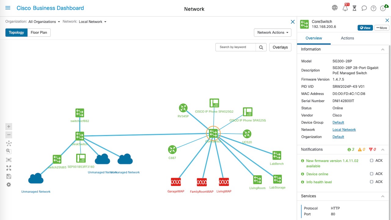
after last update of Cisco Business Dashboard tool network topology window has changed - now topology arranges by itself and I can't move any device on the diagram so this topology is totally illegible and basically useless for me.
Does anyone know that there's any possibility to rearrange devices on topology diagram or if Cisco plans to restore this feature in future updates?
In attachment you can find screenshots of old and new topology window found in Cisco documentation.
Thanks in advance for all answers!
BR
Solved! Go to Solution.
- Labels:
-
Cisco Business Dashboard
Accepted Solutions
- Mark as New
- Bookmark
- Subscribe
- Mute
- Subscribe to RSS Feed
- Permalink
- Report Inappropriate Content
04-28-2025 11:24 PM
"The new CBD version 2.10.0 has been released. In this version, the issue of somewhat messy layouts when there are loops in the topology has been optimized. Previously, we noticed that your environment had several loops, so you may want to try upgrading to the latest version to see if the layout improves."
- Mark as New
- Bookmark
- Subscribe
- Mute
- Subscribe to RSS Feed
- Permalink
- Report Inappropriate Content
02-13-2025 01:17 AM
Thank you for the feedback. The recent update to the network topology window is part of unifying the topology display across Cisco product lines. I have forwarded your feedback to the CBD product team and relevant teams for consideration in future updates.
- Mark as New
- Bookmark
- Subscribe
- Mute
- Subscribe to RSS Feed
- Permalink
- Report Inappropriate Content
02-13-2025 01:42 AM - edited 02-13-2025 01:59 AM
First of all, we sincerely apologize for any inconvenience caused by the changes in the latest version. in the new version, we no longer support user-defined topology. In the previous versions, the topology layout algorithm was not well-optimized, resulting in unreasonable layouts. In more complex networks, issues such as overlapping lines and uneven spacing between device icons could occur. To address this, we provided an additional feature that allowed users to manually drag icons to further adjust the topology layout.
However, in the latest version, we have improved the topology layout algorithm, enabling it to better present the entire network topology in a tree structure. Could you let us know what issues you are experiencing with the current tree-structured topology?Which aspects of the current topology layout algorithm are not effectively representing your actual network? we highly appreciate and look forward to your valuable feedback, so we can propose better solutions based on your specific needs.
- Mark as New
- Bookmark
- Subscribe
- Mute
- Subscribe to RSS Feed
- Permalink
- Report Inappropriate Content
02-13-2025 05:20 AM
Hi @Mark Fang, @clarkwa,
thanks for your answers. I understand that after update rearranging of devices by moving them on the topology are no longer supported.
I don't really notice a specific technical problem with current topology - from logical point of view all connections are showed correctly. The problem is the inability to change the arrangement of devices according to my needs - e.g. two switches are physically in the same place, but on the topology they're showed on different, random places (Spanning Tree are setup correctly on every switch). I was using old diagram to quickly assess the status of the network, but I can't do that right now because the devices and connections are mixed up.
For me it would be great if this feature will be restored.
- Mark as New
- Bookmark
- Subscribe
- Mute
- Subscribe to RSS Feed
- Permalink
- Report Inappropriate Content
02-13-2025 04:44 PM - edited 02-13-2025 04:45 PM
Could you take a screenshot of your topology diagram? Also could you help to point out which two devices that are physically in the same location have been placed in different positions in the layout? this will help me better understand your requirements.
In fact, according to the current tree layout algorithm, devices with closer connections are positioned closer to each other in the topology.
- Mark as New
- Bookmark
- Subscribe
- Mute
- Subscribe to RSS Feed
- Permalink
- Report Inappropriate Content
02-13-2025 11:37 PM
It's hard to take a screenshot of specific network part, so I'm attaching whole network.
As you can see there are 3 core switches (PDC-CORE1, PDC-CORE2 and PDC-CORE3) - those switches should be closest to each other on the top of the diagram. Every other switch connected to PDC-CORE2 or PDC-CORE3 should be lower. Also for example in my network switches MWS-SOC-SW1 and MWS-MAG-SW1 are placed very close to each other which was presented on my old diagram and now they're in other places. In that case however I can imagine that dashboard don't have any information on which device are places physically next to each other. You can also see my router on this diagram and industrial switches behind it - those part of network should not be mixed up with rest of devices.
I'm also attaching the pattern of how I think the switches should be arranged on the new diagram.
- Mark as New
- Bookmark
- Subscribe
- Mute
- Subscribe to RSS Feed
- Permalink
- Report Inappropriate Content
02-14-2025 12:45 AM
Do you try "Reselect new root" operation? It allows you to position specific device at the top of the layout, you can make "PDC-CORE" as the root, try this operation and see if it improves your topology layout.

"You can also see my router on this diagram and industrial switches behind it - those part of network should not be mixed up with rest of devices." Could you describe this issue in more detail? Which devices in this part of the network are being mixed up with other devices?
- Mark as New
- Bookmark
- Subscribe
- Mute
- Subscribe to RSS Feed
- Permalink
- Report Inappropriate Content
02-14-2025 12:54 AM
This option doesn't change anything. When I click on it topology looks the same as before.
Industrial network is behind FortiGate firewall which is connected to PDC-CORE1 switch (for the security reasons) and consists of one main switch (PDC-OT1) and few switches placed in every building - these are also Cisco switches. On the topology diagram those switches are mixed up with one of the FortiGates and are not clearly separated from other devices connected to PDC-CORE2 switch.
- Mark as New
- Bookmark
- Subscribe
- Mute
- Subscribe to RSS Feed
- Permalink
- Report Inappropriate Content
02-14-2025 02:04 AM

Do you specific the device before click the "Re-select new root" button?
- Mark as New
- Bookmark
- Subscribe
- Mute
- Subscribe to RSS Feed
- Permalink
- Report Inappropriate Content
02-14-2025 02:26 AM
Yes, it doesn't make any difference.
- Mark as New
- Bookmark
- Subscribe
- Mute
- Subscribe to RSS Feed
- Permalink
- Report Inappropriate Content
02-16-2025 05:55 PM
I noticed that there are five circles in your topology. Do these circles actually exist? Currently, the tree layout algorithm does have some limitations when handling network circles, which may result in an imperfect layout.


- Mark as New
- Bookmark
- Subscribe
- Mute
- Subscribe to RSS Feed
- Permalink
- Report Inappropriate Content
02-17-2025 03:32 AM
Yes, these circles are present in our network due to protection against damage to individual links. We're planning to connect all switches into ring like this. Previous topology had no problems with presentation of such connections (example below):

- Mark as New
- Bookmark
- Subscribe
- Mute
- Subscribe to RSS Feed
- Permalink
- Report Inappropriate Content
02-17-2025 05:56 PM
Actually, old topology tree algorithm also have problem to handle circles, it still need user to move the device icon manually to make the layout better. Our ultimate goal is to automatically generate a well-structured topology layout, even in the presence of network circles, or allow users to make minimal manual adjustments on top of the automatically generated layout to achieve an optimal topology layout .
Could you help to follow instructions to collect topology data? Then I can use the star layout algorithm in my local test bed to test your topology to check if the star layout algorithm can make it better .
1. Open the Chrome browser and go to the topology page in the Dashboard, then right-click on a blank area of the this page, and click the "Inspect" tab.

2. After the "Inspect" show up, then choose "Network" tab, and choose "Fetch/XHR" sub-tab.

3. Click browser refresh button to reload the page, then the browser will send an API request to the CBD backend for topology data. First, locate the corresponding topology API request(Refer to the pic for details on the specific API.). Second, click the "Preview" tab to view its response data. Third, right-click the response data to copy the data and save to your local PC, then send the data file to me.

BTW: Your help and feedback are making our product better and better. Thank you again for your support!
- Mark as New
- Bookmark
- Subscribe
- Mute
- Subscribe to RSS Feed
- Permalink
- Report Inappropriate Content
02-18-2025 06:03 AM
I would like not to send this file on public community site. Is it possible to send it to you by private message or email?
- Mark as New
- Bookmark
- Subscribe
- Mute
- Subscribe to RSS Feed
- Permalink
- Report Inappropriate Content
02-18-2025 05:09 PM
Sure, you can send to my email "clarkwa@cisco.com".
Discover and save your favorite ideas. Come back to expert answers, step-by-step guides, recent topics, and more.
New here? Get started with these tips. How to use Community New member guide