- Cisco Community
- Technology and Support
- Collaboration
- Collaboration Knowledge Base
- Preserving TelePresence Quality over the WAN with Performance Routing (PfR)
- Subscribe to RSS Feed
- Mark as New
- Mark as Read
- Bookmark
- Subscribe
- Printer Friendly Page
- Report Inappropriate Content
- Subscribe to RSS Feed
- Mark as New
- Mark as Read
- Bookmark
- Subscribe
- Printer Friendly Page
- Report Inappropriate Content
04-27-2011 06:58 AM - edited 03-12-2019 09:37 AM
Having suffered through many videoconferences where choppy audio and pixelated video turned an all-hands meeting into a frantic troubleshooting drill, I was somewhat skeptical that my first Cisco TelePresence experience would meet the promise of being “as good as being in the same room with the other participants.” Despite all the impressive technology behind the solution, I remained a skeptic until I attended my first conference during a customer design workshop held over TelePresence between Cisco offices in North Carolina, New York, and London. After the initial shock, awe, and bad jokes, “When will Cisco be coming out with SmellaPresence”?, I was amazed how quickly everyone was able to focus the meeting goals instead of the medium we were using to communicate. As a user of TelePresence I immediately recognized a killer app for video collaboration, but as designer of networks I wondered if I might soon be facing a WAN killer!
From a network perspective, Cisco TelePresence demands stringent service level requirements for loss, latency, and jitter, more so than most applications on the network. These network demands are well documented in the Cisco TelePresence Network Systems 2.0 Design Guide, which serves as an invaluable reference for QoS design, platform selection and bandwidth provisioning for campus and branch deployments. The service level requirements for Cisco TelePresence as compared to generic videoconferencing and Cisco VoIP are summarized in Table 1.
Table 1: Cisco TelePresence Newtork Service Level Requirements compared to VoIP and Generic Videoconferencing
| Service Level Parameter | (Generic) Videoconferencing | Cisco TelePresence | VoIP |
|---|---|---|---|
Bandwidth | 84 kbps or 768 kbps +network overhead | 1.5 Mbps to 12.6 Mbps +network overhead | 21 to 320 kbps + network overhead per call |
| Latency | 400-450 ms latency | 150 ms latency | 150 ms latency |
| Jitter | 30-50 ms peak-to-peak jitter | 10 ms peak-to-peak jitter | 30 ms peak-to-peak jitter |
| Loss | 1% random packet loss | 0.05% random packet loss | 1% random packet loss |
As evidenced in table 1, the network characteristics to provide HD video quality is different and, in some cases, more stringent than for VoIP. In general, VoIP is more tolerant to packet loss than video, while video is more forgiving to latency and jitter than VoIP. Packet loss presents a much greater impairment to video quality than latency and jitter due to the high degree of compression used by the TelePresence codecs to make HD video feasible for network transmission. As an example, it takes approximately 1.5Gbps of information, per screen, to present a “best quality” (1080p30) TelePresence video stream. In order to make this practical for deployment on a converged network, H.264-based TelePresence codecs transmit this information at under 5 Mbps per screen, which translates to over 99% compression. The end result is that dropping even one packet in 10,000 (0.01% packet loss) is noticeable to end users in the form of pixelated video. VoIP codecs, on the other hand include packet loss concealment (PLC) algorithms that hide the loss of a single voice packet by playing out the last video sample, giving 1% tolerance for loss. From an end-user perspective, this makes TelePresence 100 times more sensitive to packet loss than VoIP!
Provisioning a dedicated network for Cisco TelePresence is obviously an option, but typically cost prohibitive for most enterprise organizations that are users, rather than providers of the service. The customer benefit of running TelePresence on a converged network (as opposed to an overlay network) is that 90% of the time TelePresence will use far less than what the network is provisioned for, and hence data traffic can flow at higher rates, taking advantage of the unused bandwidth. But when the TelePresence traffic does burst, the network must be properly provisioned to handle it, hence preserving the experience.
TelePresence Converged Network Deployment Models
The Cisco TelePresence Network Systems 2.0 Design Guide presents a detailed description of the technical solution, providing provisioning and logical design guidance for several converged network deployment models.
Intra-Campus TelePresence Network Deployment
This is the simplest model, and one that most enterprise customers often deploy as a pilot, or first rollout of Cisco TelePresence. This deployment model is applicable for enterprises that have a large number of buildings within a given campus and employees who are often required to drive to several different buildings during the course of the day to attend meetings. The network infrastructure of an intra-campus deployment model is expected to be predominantly Cisco Catalyst switches connecting via 1-Gig Ethernet or 10-Gig Ethernet links with a high degree of meshing, and call signaling as shown in figure 1:
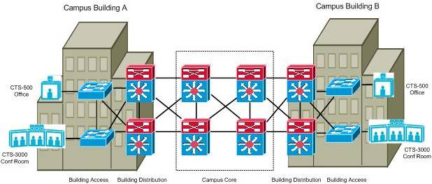
Figure 1: Example Intro-Campus TelePresence Deployment Model
Most campus environments are generally very well suited to meet the network demands of Cisco TelePresence, thanks to an abundance of bandwidth and end-to-end transmission paths that introduce very little latency or jitter during normal operating conditions. Packet loss attributed to circuit or equipment failures is generally low in a campus environment due to a high degree of network redundancy and the fast converging characteristics of an IGP routing protocol such as OSPF or EIGRP that is commonly deployed. A rich set of Campus QoS features are available for the Catalyst platforms, which when deployed properly, can offer priority treatment for the real time audio and video packets during periods of link congestion.
Intra-Enterprise Network Deployment (LAN and WAN)
The intra-enterprise model expands on the intra-campus model to include sites connected over a Wide Area or Metro Area Network with typical circuit speeds of less than 1-Gig Ethernet. The network infrastructure of a typical intra-enterprise deployment model would include a combination of Cisco Catalyst switches within the campus and Cisco routers over the WAN, which may include private IP WANs, MPLS VPNs, or Metro Ethernet networks. Typical WAN/MAN speeds at medium to large sites may include 45 Mbps/T3 circuits, and from sub-rate up to Gigabit Ethernet. An example of the Intra-Enterprise TelePresence Deployment model is shown in figure 2 below:
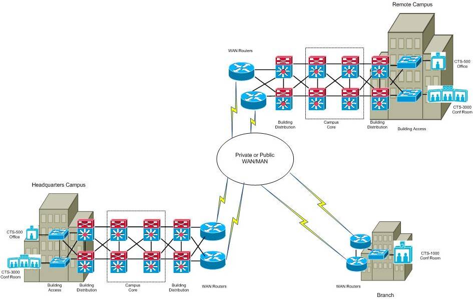
Figure 2: Example Intra-Enterprise TelePresence Deployment Model
The intra-enterprise model presents challenges and considerations for TelePresence deployments across a WAN that are non-issues in a campus environment. Circuit congestion is more common in the WAN, as the costs and availability of Gigabit bandwidth speeds are generally prohibitive, and lower speeds are more common. In many instances circuit congestion often causes packet loss, particularly when QoS features are not provisioned properly, adequately, or consistently end to end. Packet loss across a corporate WANs built upon a service provider IP or MPLS backbone can increase unexpectedly as the number of subscribers in a particular area drastically increases, or when micro-bursts of traffic overwhelm packet buffers and tail dropping occurs. Packet loss attributed to device or circuit failures is also generally higher in WAN environments, as the commonly deployed BGP routing protocol was fundamentally not designed to converge as quickly as OSPF or EIGRP.
Inter-Enterprise/Business-to-Business
The inter-enterprise network deployment model allows for TelePresence systems within one enterprise to call systems within another enterprise. The inter-enterprise model is also referred to as the business-to-business (B2B) TelePresence deployment model. The network infrastructure of the inter-enterprise/B2B deployment model builds on the intra-enterprise model and commonly requires the enterprises to share a common MPLS VPN service provider (SP). The MPLS VPN SP would typically provision a “shared services” Virtual Routing and Forwarding (VRF) instance where Cisco IOS XR Session/Border Controller (SBC) would be hosted to provide inter-VPN communications and control plane signaling between the enterprises.
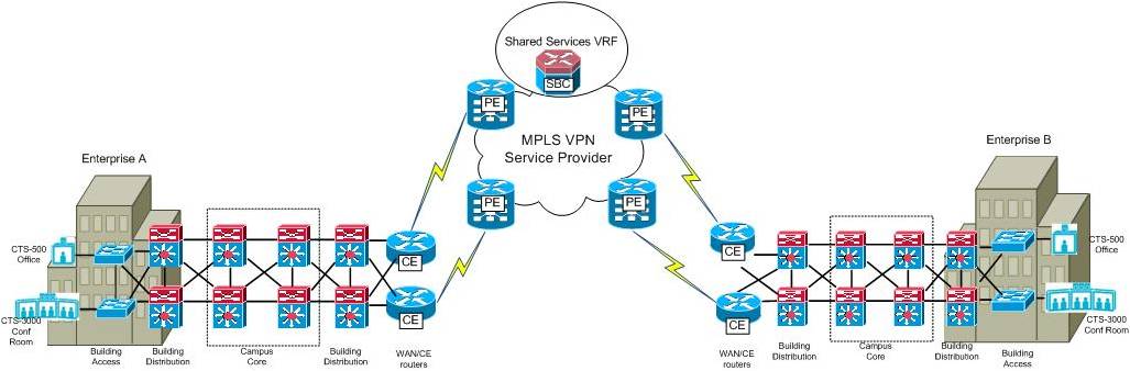
Figure 3: Example Inter-Enterprise (B2B) TelePresence Deployment Model
The B2B model presents all of same network challenges discussed in the Intra-Enterprise model and then some. In general, Enterprise WANs built upon MPLS/VPN fabrics are often more prone to packet loss attributed to provider “cloud” routing convergence and “soft failures” which are defined as degraded conditions that are not detected by the CE-PE routing protocols. To complicate matters, SP MPLS/VPN QoS contracts are typically only offered from a “point-to-cloud” perspective, rather than end to end. This requires very careful planning and coordination between the engineers in each enterprise and the service provider in order to be accurately deployed and effective.
Executive Home (Internet/IPSec VPN)
Due to the high executive-perk appeal of TelePresence and the availability of high-speed residential bandwidth options, some executives have begun to deploy TelePresence units in their home offices, usually over an IPSec VPN tunnel to a corporate office.

Figure 4: TelePresence to the Executive Home (IPSEC VPN)
Deploying Cisco TelePresence across an IPSec VPN WAN to a residence presents many of the same challenges as discussed in the previous sections. Lower bandwidth, higher latency and jitter, and relatively higher levels of packet loss are more common with IPSec solutions that tunnel over ISP/Internet backbones.
Choosing a WAN Path of Least Resistance
Anyone with a basic understanding of physics knows that objects will follow the path of least resistance. Water flowing downhill will follow the path of least resistance as it is pulled downhill by gravity. Electricity flowing through the atmosphere or a circuit behaves similarly. In contrast, IP packets do not possess an innate sense of which network path will offer the least resistance, and instead blindly follow a path chosen for them by a routing protocol with no knowledge of dynamics, taking into account only static metrics. Quality of Service (QoS) technologies, while necessary to prioritize the delivery of real time packets on congested links, do not create bandwidth or solve the problem of preserving network packets are “in flight” and subject to being dropped across a “dirty” path. Selecting a “clean” network path is only possible if the routing protocol has more information available to it than static metrics. This is the premise of Performance Routing, an IOS solution that is available to choose the best performing WAN path, as opposed to simply the shortest path.
Introduction to Performance Routing (PfR)
Performance Routing (PfR) is an integrated Cisco IOS solution that enhances traditional routing by using the intelligence of imbedded Cisco IOS features to improve application performance and availability. PfR can be configured to monitor IP traffic flows, measure WAN path performance, and dynamically reroute traffic when network conditions degrade or when user-defined policies dictate specific WAN exit points. PfR is able to make intelligent routing decisions based on real-time feedback from IOS reporting sources such as NetFlow data records, IP SLA statistics, and WAN link utilization, thus enabling an application-aware routing capability not possible with traditional routing protocols such as OSPF or BGP that are limited to one-dimensional metrics to choose a “best path”.
The functional components of PfR include Master Controllers (MC) and Border Routers (BR). The MC is the device (Cisco router) where customer policies are applied, link utilization and path performance is evaluated, and re-routing decisions are made. BRs are WAN routers in the forwarding path where applications are learned, measurement probes are sent from, and enforcement of traffic routing is applied. through PfR-installed routing table updates (static, dynamic or PBR). The PfR infrastructure includes a performance routing protocol that is communicated in a client-server messaging mode between MC and BR to create a network performance loop in order to select the best path for different classes of traffic. The PfR performance loop starts with the profile phase followed by the measure, apply policy, control, and verify phases. The loop continues after the verify phase back to the profile phase to update the traffic classes and cycle through the process. Figure 5 shows the five PfR phases: profile, measure, apply policy, enforce, and verify.
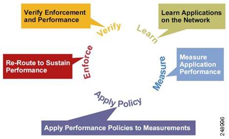
Figure 5: PfR Network Performance Loop
PfR for TelePresence Availability Across the WAN
This section illustrates how PfR can be deployed to preserve TelePresence quality by detecting and rerouting around an impaired WAN path. The topology for this discussion is shown in Figure 6, which is an adaptation of the inter-Enterprise WAN deployment model from the Cisco TelePresence Network Systems 2.0 Design Guide.
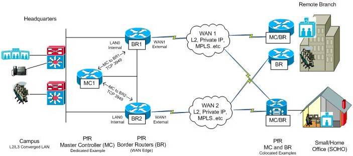
Figure 6: PfR Topology for a TelePresence WAN Deployment
A dedicated Master Controller (MC1) is shown at the HQ location to control BR1 and BR2, which are the WAN edge routers. The decision to deploy a dedicated MC at the HQ site was made in this example based on the expectation that PfR will be used to control more than just TelePresence across in the future, and it is considered best practice to deploy a dedicated MC at a HQ site with a medium to large sized WAN. As a general rule if you need to control more than 1000 traffic classes, it is recommended that you configure a dedicated Master controller. For branch deployments, or small/home office (SOHO) setups, it is normally acceptable if the Master Controller and the Border Router coexist on the same physical router.
PfR deployment considerations for this scenario include the following:
- Profile Traffic as TelePresence: PfR is able to identify or profile interesting traffic either through NetFlow (learning) from actual flows through the BRs, or through explicit configuration. Since QoS best practices for TelePresence are well documented and widely followed, it is possible to explicitly configure an extended access-list that matches CS3 (TP Call Signaling) or CS4 (TP video) on the MC.
- Policy Configuration for TelePresence: PfR policies specify the performance service level parameters that pertain to specific traffic class. These policies are used by the MC to determine when a prefix or application out of policy across a certain WAN path, and re-routing to a better path is desired. A PfR policy for TelePresence can be derived from the network service level parameters identified in the Cisco TelePresence Network Systems 2.0 Design Guide.
- Performance Monitoring of TelePresence: There are two mechanisms for measuring performance with PfR; “passively” monitoring TCP flags of actual flows traversing through a Border Routers using an embedded NetFlow mechanism within PfR, or “actively” monitoring the WAN paths by generating synthetic traffic using IP Service Level Agreements (SLAs) that emulate the traffic class that is being monitored. With TelePresence (as with VoIP), it is necessary to actively monitor paths since it is the only way to proactively measure the quality all possible paths to achieve fast reroute. Also, it is not possible to obtain jitter or delay metrics from NetFlow information in this case, as Video RTP traffic is UDP-based.
Figure 7 examines the PfR in action during steady state network conditions when no impairments are occurring. In this example, TelePresence traffic is forwarded from the HQ to branch facility following the normal routing path selected by a traditional routing protocol.
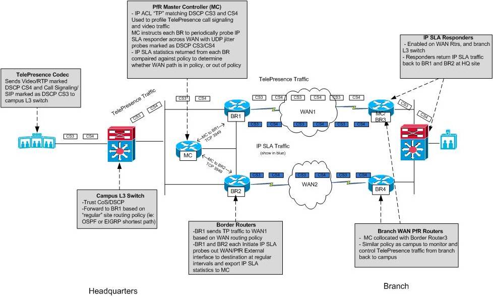
Figure 7: PfR Profiling and Performance Measurement of TelePresence with IP SLA
Figure 8 below shows how PfR detects impairment across a primary WAN path and reroutes TelePresence traffic across a better performing path
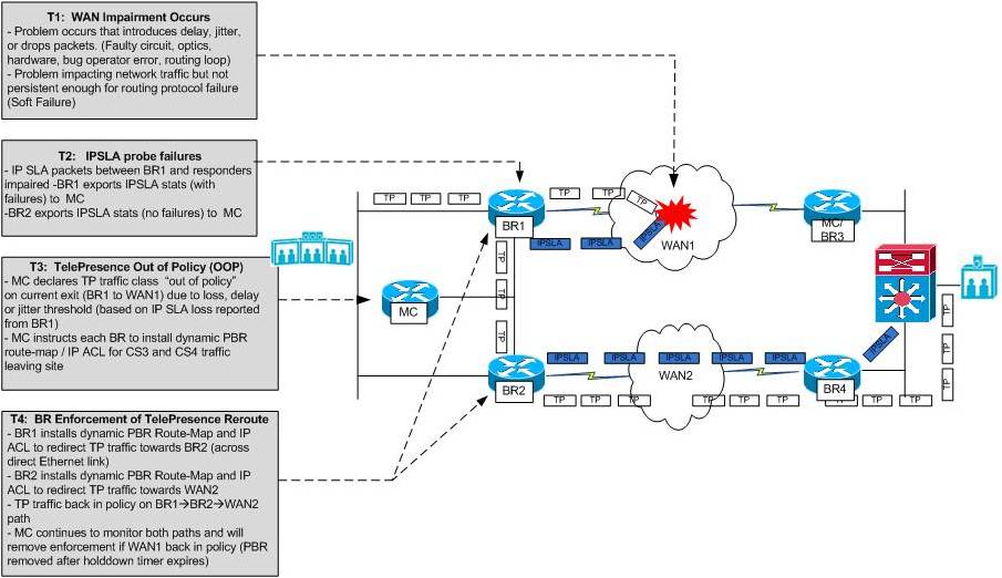
Figure 8: PfR Rerouting TelePresence around an Impaired WAN Path
PfR Configuration
The following configuration samples of MC1 and BR1/BR2 at the HQ site are provided as an example of how outbound PfR application optimization of TelePresence as shown in this example could be achieved. A similar configuration would be implemented on the branch routers (BR3 and BR4), the difference being that the MC function could be collocated onto one of them instead of deploying an dedicated MC device.
It should be mentioned that there is a requirement for a parent route be present in each border router (BR1/BR2) routing table for the destination network in order for a traffic class to be monitored and controlled by PfR. This parent route could be satisfied with a static or dynamic default route. (0.0.0.0/0.0.0.0). Also, the direct interconnection between both Border Routers at the site is necessary for PfR applicaton optimization, which leverages dynamic Policy Based Routing (PBR). This prerequisite could be met with physical link as shown, or a GRE tunnel between the Border Routers if the topology does not include a direct link.
MC1 PfR Configurations
!
hostname MC1
!
! This is the basic configuration required to establish session between MC and BR
! It includes
!
! Key-chain configuration for authentication.
! Specification of BR’s IP Address and internal/external interface on each BR
! Logging to enable verbose MC syslog information
! Named Policy “PfR_Policy” invoked for customized traffic class policies
!
key chain PfR
key 10
key-string 7 xxxxxx
!
!
! The following configurations
!
key chain oer
key 1
key-string oer
oer master
policy-rules PfR_Policy
logging
!
border 1.1.1.1 key-chain oer
interface Ethernet1/0 internal
interface Ethernet0/0 internal
interface Serial2/0 external
!
border 2.2.2.2 key-chain oer
interface Serial2/0 external
interface Ethernet0/0 internal
interface Ethernet1/0 internal
no max range receive
holddown 90
!
!
! This is a PfR policy configuration for TelePresence specific to one branch. This
! should be repeated for every branch having TelePresence. It includes:
!
!
! match command is to specify that this policy should be applied to the traffic
! class configured under extended access-list TP (matching dscp cs3/cs4)
!
! Mode route control is necessary for PfR to reroute traffic to better path when
! OOP condition detected. Default is route observe which does not enforce reroute.
!
! Loss threshold is set to 50000 packets-per-million (5%). This is the lowest level of loss that can be reliably be
! detected with current IP SLA active probing techniques
!
! Jitter threshold 10 msec.
!
! Delay threshold is set to 300 ms. The delay measured by PfR is Round-Trip-Time
! and TelePresence delay SLA is 150ms
!
! monitor mode is set to fast. This means probe all external interfaces all the
! time. When Out-of-Policy condition is detected on the current exit results on
! alternate exit is available for quick decision. In other modes alternate
! exits are probed only when current link is determined to be OOP. The fast mode
! helps in switching the path
! quickly when the problem is detected
!
! The order of priority is set to loss, jitter and delay based on the impact
! each metrics could have on TelePresence
!
! The probe type is jitter because only jitter probe can measure loss/jitter/delay.
! Three IP SLA responders are probed at each branch (WAN routers and LAN Switch) to provide a better sample
!
! Probe frequency is set to 4 second to detect the problem quickly. For
! critical application such as video a lower probe frequency is desirable.
!
oer-map PfR_Policy 10
match traffic-class access-list TP
set mode select-exit best
set delay threshold 300
set mode route control
set mode monitor fast
set resolve loss priority 1 variance 5
set resolve jitter priority 2 variance 5
set resolve delay priority 3 variance 5
no set resolve utilization
set loss threshold 50000
set jitter threshold 10
set active-probe jitter 20.1.1.1 target-port 2002
set active-probe jitter 40.1.1.1 target-port 2003
set active-probe jitter 50.1.1.1 target-port 2003
set probe frequency 4
!
ip access-list extended TP
permit ip any any dscp cs3
permit ip any any dscp cs4
!
end
As compared to the Master Controller configuration, the border router configurations are very simple.
BR1 and BR2 Router PfR Configurations
! This is the basic configuration required to establish session between BR and MC.
! It includes
!
! Key-chain configuration for authentication.
! Specification of MC IP Address
! Specification of BR local address – Must match what is configured on MC
! Logging to enable verbose BR syslog information
key chain PfR
key 10
key-string 7 xxxxxx
oer border
logging
local Loopback0
master 3.3.3.3 key-chain PfR
The examples below show how the IP SLA responder feature would be enabled on an IOS router, in this example the BR3 and BR4 routers at the remote branch.
Remote Branch Router IP SLA Responder Configuration
ip sla responder
Monitoring PfR in Action – MC and BR output
To view the current state of the PfR traffic-classes, issue the show oer master traffic class command from the MC. In the output below, there are several items of interest. First, the prefix is in HOLDDOWN state. This is because the route for the traffic class has recently changed with PBR. PfR traffic classes are always placed in HOLDDOWN state to avoid oscillation between Border Routers and possible destabilization of the network-wide routing tables. The current exit interface for the traffic classes (Serial2/0 on 2.2.2.2/BR2) is shown and this can also be verified by viewing the routing table, or PBR. The short-term active delay and jitter is 31ms/31ms for CS4 IP SLA probes and 32ms/32ms for CS3 IP SLA probes, respectively.
MC#show oer mas traffic-class
OER Prefix Statistics:
Pas - Passive, Act - Active, S - Short term, L - Long term, Dly - Delay (ms),
P - Percentage below threshold, Jit - Jitter (ms),
MOS - Mean Opinion Score
Los - Packet Loss (packets-per-million), Un - Unreachable (flows-per-million),
E - Egress, I - Ingress, Bw - Bandwidth (kbps), N - Not applicable
U - unknown, * - uncontrolled, + - control more specific, @ - active probe all
# - Prefix monitor mode is Special, & - Blackholed Prefix
% - Force Next-Hop, ^ - Prefix is denied
DstPrefix Appl_ID Dscp Prot SrcPort DstPort SrcPrefix
Flags State Time CurrBR CurrI/F Protocol
PasSDly PasLDly PasSUn PasLUn PasSLos PasLLos EBw IBw
ActSDly ActLDly ActSUn ActLUn ActSJit ActPMOS
--------------------------------------------------------------------------------
0.0.0.0/0 N cs4 256 N N 0.0.0.0/0
HOLDDOWN @77 2.2.2.2 Se2/0 PBR
N N N N N N N N
31 31 0 0 5 0
0.0.0.0/0 N cs3 256 N N 0.0.0.0/0
HOLDDOWN @70 2.2.2.2 Se2/0 PBR
N N N N N N N N
32 32 0 0 5 0
The IP SLA probe status can be retrieved from each Border Router with “show oer border active-probes”. Each BR at HQ initiates two probes to each of the three targets at the branch site (WAN routers and LAN switch) on a period basis. One probe is marked as TOS 96 (DSCP CS3) and the other as TOS 128 (DSCP CS4). Detailed IP SLA statistics for each probe can be retrieved with “show ip sla statistics”, as shown below.
BR1#show oer bor active-probes
OER Border active-probes
Type = Probe Type
Target = Target IP Address
TPort = Target Port
Source = Send From Source IP Address
Interface = Exit interface
Att = Number of Attempts
Comps = Number of completions
N - Not applicable
Type Target TPort Source Interface Att Comps
DSCP
jitter 20.1.1.1 2000 10.4.1.1 Se2/0 266 22025
96
jitter 40.1.1.1 2000 10.4.1.1 Se2/0 266 22035
96
jitter 50.1.1.1 2000 10.4.1.1 Se2/0 266 22033
96
jitter 20.1.1.1 2000 10.4.1.1 Se2/0 266 22143
128
jitter 40.1.1.1 2000 10.4.1.1 Se2/0 266 22127
128
jitter 50.1.1.1 2000 10.4.1.1 Se2/0 267 22275
128
BR2#show oer bor active-probes
OER Border active-probes
Type = Probe Type
Target = Target IP Address
TPort = Target Port
Source = Send From Source IP Address
Interface = Exit interface
Att = Number of Attempts
Comps = Number of completions
N - Not applicable
Type Target TPort Source Interface Att Comps
DSCP
jitter 20.1.1.1 2000 10.5.1.2 Se2/0 292 26807
96
jitter 40.1.1.1 2000 10.5.1.2 Se2/0 291 27114
96
jitter 50.1.1.1 2000 10.5.1.2 Se2/0 296 27330
96
jitter 20.1.1.1 2000 10.5.1.2 Se2/0 294 27059
128
jitter 40.1.1.1 2000 10.5.1.2 Se2/0 291 26797
128
jitter 50.1.1.1 2000 10.5.1.2 Se2/0 293 27276
128
BR1#show ip sla statistics
Round Trip Time (RTT) for Index 131
Latest RTT: 33 milliseconds
Latest operation start time: *16:50:36.183 EST Thu Apr 7 2011
Latest operation return code: OK
RTT Values:
Number Of RTT: 82 RTT Min/Avg/Max: 13/33/89 milliseconds
Latency one-way time:
Number of Latency one-way Samples: 0
Source to Destination Latency one way Min/Avg/Max: 0/0/0 milliseconds
Destination to Source Latency one way Min/Avg/Max: 0/0/0 milliseconds
Jitter Time:
Number of SD Jitter Samples: 81
Number of DS Jitter Samples: 81
Source to Destination Jitter Min/Avg/Max: 0/15/47 milliseconds
Destination to Source Jitter Min/Avg/Max: 0/4/11 milliseconds
Packet Loss Values:
Loss Source to Destination: 0 Loss Destination to Source: 0
Out Of Sequence: 0 Tail Drop: 0
Packet Late Arrival: 0 Packet Skipped: 18
Voice Score Values:
Calculated Planning Impairment Factor (ICPIF): 0
Mean Opinion Score (MOS): 0
Number of successes: 290
Number of failures: 0
Operation time to live: Forever
PfR enforcement of policy is achieved through dynamic PBR on each Border Router. The PBR next hops for each traffic class can be displayed on the Border Routers using “show route-map dynamic” with the corresponding dynamic IP ACL shown with “show ip access-list dynamic” as shown below:
BR1#show route-map dynamic
route-map OER-04/06/11-19:59:57.439-1-OER, permit, sequence 0, identifier 45960512
Match clauses:
ip address (access-lists): oer#1
Set clauses:
ip next-hop 10.1.1.2
interface Ethernet0/0
Policy routing matches: 15 packets, 1710 bytes
Current active dynamic routemaps = 1
Inet-BR1#show ip access-lists dynamic
Extended IP access list oer#1
536870911 permit ip any any dscp cs3 (10 matches)
1073741823 permit ip any any dscp cs4 (5 matches)
Inet-BR1#
BR2#show route-map dynamic
route-map OER-04/06/11-19:59:57.275-1-OER, permit, sequence 0, identifier 52329408
Match clauses:
ip address (access-lists): oer#1
Set clauses:
ip next-hop 10.5.1.1
interface Serial2/0
Policy routing matches: 15 packets, 1710 bytes
Current active dynamic routemaps = 1
Inet-BR2#show ip access-list dynamic
Extended IP access list oer#1
536870911 permit ip any any dscp cs3 (10 matches)
1073741823 permit ip any any dscp cs4 (5 matches)
Output from the previous examples verified that traffic was flowing through the BR2 router (2.2.2.2), while the network was operating in steady state. In the next example, a WAN impairment occurs that causes packets to be dropped on the primary path (BR2 to WAN2). This impairment affects not only application but IP SLA packets originated from BR2. The following SYSLOG message from the MC indicates “unreachable OOP” due to IP SLA loss, and that a route change has occurred for each traffic class to BR1 (1.1.1.1). This can be verified again with “show oer master traffic-class” on the MC, and “show route-map dynamic” on each BR as shown below:”
MC#
*Apr 7 15:01:31.347: %OER_MC-5-NOTICE: Active REL Unreachable OOP Appl Prefix 0.0.0.0/0 cs4 256, unreachable 125000, BR 2.2.2.2, i/f Se2/0, relative change 200, prev BR Unknown i/f Unknown
*Apr 7 15:01:31.563: %OER_MC-5-NOTICE: Route changed Appl Prefix 0.0.0.0/0 cs4 256, BR 1.1.1.1, i/f Se2/0, Reason Unreachable, OOP Reason Unreachable
*Apr 7 15:02:16.175: %OER_MC-5-NOTICE: Active REL Unreachable OOP Appl Prefix 0.0.0.0/0 cs3 256, unreachable 166666, BR 2.2.2.2, i/f Se2/0, relative change 933, prev BR Unknown i/f Unknown
*Apr 7 15:02:16.179: %OER_MC-5-NOTICE: Route changed Appl Prefix 0.0.0.0/0 cs3 256, BR 1.1.1.1, i/f Se2/0, Reason Unreachable, OOP Reason Unreachable
MC#show oer master traffic-class
OER Prefix Statistics:
Pas - Passive, Act - Active, S - Short term, L - Long term, Dly - Delay (ms),
P - Percentage below threshold, Jit - Jitter (ms),
MOS - Mean Opinion Score
Los - Packet Loss (packets-per-million), Un - Unreachable (flows-per-million),
E - Egress, I - Ingress, Bw - Bandwidth (kbps), N - Not applicable
U - unknown, * - uncontrolled, + - control more specific, @ - active probe all
# - Prefix monitor mode is Special, & - Blackholed Prefix
% - Force Next-Hop, ^ - Prefix is denied
DstPrefix Appl_ID Dscp Prot SrcPort DstPort SrcPrefix
Flags State Time CurrBR CurrI/F Protocol
PasSDly PasLDly PasSUn PasLUn PasSLos PasLLos EBw IBw
ActSDly ActLDly ActSUn ActLUn ActSJit ActPMOS
--------------------------------------------------------------------------------
0.0.0.0/0 N cs4 256 N N 0.0.0.0/0
HOLDDOWN @37 1.1.1.1 Se2/0 PBR
N N N N N N N N
48 43 0 0 12 0
0.0.0.0/0 N cs3 256 N N 0.0.0.0/0
HOLDDOWN @32 1.1.1.1 Se2/0 PBR
N N N N N N N N
85 58 0 0 20 0
BR1#show route-map dynamic
route-map OER-04/07/11-14:20:20.727-4-OER, permit, sequence 0, identifier 53587208
Match clauses:
ip address (access-lists): oer#2
Set clauses:
ip next-hop 10.4.1.2
interface Serial2/0
Policy routing matches: 0 packets, 0 bytes
Current active dynamic routemaps = 1
BR1#show ip access-list dynamic
Extended IP access list oer#2
BR2#show route-map dynamic
route-map OER-04/07/11-14:20:19.939-4-OER, permit, sequence 0, identifier 45895024
Match clauses:
ip address (access-lists): oer#3
Set clauses:
ip next-hop 10.5.1.1
interface Serial2/0
Policy routing matches: 0 packets, 0 bytes
Current active dynamic routemaps = 1
BR2#
IP SLA statistics verified from each BR with “show ip sla statistics”.
BR2# show ip sla statistics
Round Trip Time (RTT) for Index 142
Latest RTT: 18 milliseconds
Latest operation start time: *17:15:24.511 EST Thu Apr 7 2011
Latest operation return code: OK
RTT Values:
Number Of RTT: 98 RTT Min/Avg/Max: 13/18/32 milliseconds
Latency one-way time:
Number of Latency one-way Samples: 0
Source to Destination Latency one way Min/Avg/Max: 0/0/0 milliseconds
Destination to Source Latency one way Min/Avg/Max: 0/0/0 milliseconds
Jitter Time:
Number of SD Jitter Samples: 95
Number of DS Jitter Samples: 95
Source to Destination Jitter Min/Avg/Max: 0/3/9 milliseconds
Destination to Source Jitter Min/Avg/Max: 0/3/12 milliseconds
Packet Loss Values:
Loss Source to Destination: 0 Loss Destination to Source: 7
Out Of Sequence: 0 Tail Drop: 0
Packet Late Arrival: 0 Packet Skipped: 0
Voice Score Values:
Calculated Planning Impairment Factor (ICPIF): 0
Mean Opinion Score (MOS): 0
Number of successes: 69
Number of failures: 2
Operation time to live: Forever
BR1#show ip sla statistics
Round Trip Time (RTT) for Index 140
Latest RTT: 46 milliseconds
Latest operation start time: *17:15:13.283 EST Thu Apr 7 2011
Latest operation return code: OK
RTT Values:
Number Of RTT: 74 RTT Min/Avg/Max: 16/46/100 milliseconds
Latency one-way time:
Number of Latency one-way Samples: 0
Source to Destination Latency one way Min/Avg/Max: 0/0/0 milliseconds
Destination to Source Latency one way Min/Avg/Max: 0/0/0 milliseconds
Jitter Time:
Number of SD Jitter Samples: 73
Number of DS Jitter Samples: 73
Source to Destination Jitter Min/Avg/Max: 0/13/51 milliseconds
Destination to Source Jitter Min/Avg/Max: 0/4/9 milliseconds
Packet Loss Values:
Loss Source to Destination: 0 Loss Destination to Source: 0
Out Of Sequence: 0 Tail Drop: 1
Packet Late Arrival: 0 Packet Skipped: 25
Voice Score Values:
Calculated Planning Impairment Factor (ICPIF): 0
Mean Opinion Score (MOS): 0
Number of successes: 67
Number of failures: 0
Operation time to live: Forever
Conclusion
Originally touted as means for cost savings through a reduction in business travel, Cisco TelePresence has actually changed the way many companies do business, allowing more frequent collaborations with vendors, partners, customers and suppliers. The need to deploy TelePresence in remote locations is causing many organizations to upgrade their WANs, adding bandwidth, enabling QoS, and enabling high availability features to minimize the impact of hardware or software failures in the network infrastructure. Cisco Performance Routing (PfR) is an advanced IOS solution that can offer application-aware routing for TelePresence, monitoring WAN path performance and dynamically rerouting traffic around impairments that could affect quality.
Find answers to your questions by entering keywords or phrases in the Search bar above. New here? Use these resources to familiarize yourself with the community: