HI,
Im hoping I can call upon the collective power of the community! Firstly, I apologise for how the question is posed, i hope i can make myself clear!
I am completing a Disaster Recovery report / design for a module, specifically focused on Network Security. Essentially, we have been given partial configs from a few devices and we need to piece what we can together. I have got a reasonably accurate idea so far, and been told its pretty close to what the "results" paper would look like.
But, something has me stumped. I wont bore people with the full config sheet but to summarise some key points:
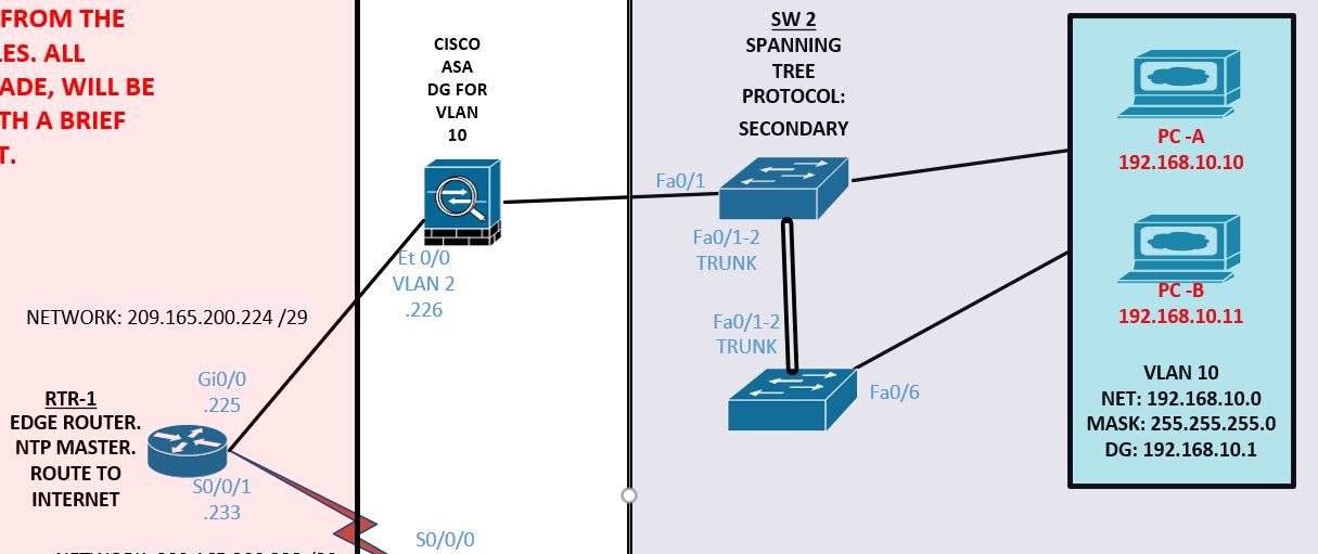
1. Two switches (SW1 and SW2) link two pc's in the same VLAN (10, subnet 192.168.10.0/24). One on each. I am confident the two switches are in the same subnet, mainly as they are operating as STP primary / secondary respectively.
2. SW2 has Fa0/18 and 24 set as access ports, portfast etc, so must be connected to end devices (although I cannot work out why there are two ports set up like this, if SW1 also has end devices connected?). SW1 does not mention any access ports being set, but the "recovery" document may be incomplete. SW1 does, however, conspicuously show you that every port other than the trunks below are shutdown EXCEPT fa0/6, which i assume is the access port connected to one of the PC's. I could be wrong though...
3. SW1 and 2 BOTH have trunk links set on fa0/1-2, and I assume they connect together.
4. I assume this because there is an ASA whose VLAN 1 is set with the default gateway ip address for the above network.
5. Now this is where i get really confused....it is made quite obvious that a router (router 2) has been missed out deliberately. (R1 is the edge rtr, and the document jumps to R3, which links up a SYSLOG network). It seems that somewhere along the line R2 must fit into the 192.168.1.0 network, but my inexperience with ASAs (especially when acting as a default gateway?) i just cannot see where.
I have attached a JPG of what I think it should look like. All i know for sure is that there must be a connection to the ASA from either one of the switches above, or from R2 possibly if we were to just accept its existence, to connect the PCs (VLAN 10) through to the edge rtr.
I appreciate anyone that has taken the time to read this, and again apologies for the confusion. Im not looking for "the answer" as such, as really there isnt a perfect one, more for inspiration. An angle i might have missed, a port used in a different way, how R2 could possibly interact etc.
Thanks again!
