- Subscribe to RSS Feed
- Mark as New
- Mark as Read
- Bookmark
- Subscribe
- Printer Friendly Page
- Report Inappropriate Content
12-18-2009 11:26 PM - edited 03-01-2019 04:28 PM
Introduction
Network Address Translation is a very common feature used to address some issues and also to meet some networks' requirements such as, overlapped networks and Internet links.
In this small document we will discuss a business requirement example, and the main idea behind this example is to demonstrate how to implement and configure NATign with dual homed Internet edge Router in conjunction with other Cisco IOS advanced features (Policy Based routing PBR and IPSLA ).
Also we will see how all of the above mentioned features work together and how IP SLA will work like a gear to this implementation in term of controlling the exit path of the traffic by controlling the default route in the routing table and PBR decision.
Requirements:
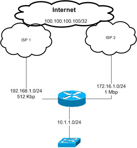
Company XYZ.com has bought a second Internet connection with 1 Mbps in addition to the existing one with 512 Kbps.
the requirement is to load share the traffic over those two links
web traffic and telnet traffic must use the the new ISP link ISP2 and all other traffic must go thorough the old ISP link ISP1
in the case of any of the above links gose down all the traffic should use the remaining link
Note:
this example has been configured in a lab environment and al the private ip addresses used in this document just for the purpose of this example
Proposed solution:
According to the above requirements we will use Policy Based routing feature to control LAN traffic going to the Internet and which path to use.
all traffic from the LAN subnet 10.1.1.0/24 destined to tcp 23, 80 and 443 must be routed to ISP 2 link with next hop 172.16.1.2
all other traffic will go though ISP 2 with next hop of 192.168.1.2
as we do not have any subnet or ip ranges to use it over the Internet we have to use NATing with overload option to use the Internet interface IP address
of each ISP link
for example traffic going through ISP 1 will be seen by ISP one and the Internet as it is from 192.168.1.1
if it is through ISP 2 will be seen as it is from 172.16.1.1
In the case of one of the links go down we need all the traffic to use the other remaining link
this will be archived here by using IP SLA with ICMP echo that will be sent to each of the ISP next hop IP addresses in our example 192.168.1.2 and 172.16.1.2
the ICMP echo will be sent every 1 second with time out of 500 msec
if the icmp reply not heard from any of those next hops within 1 second that link will be considered down and the default route in the Internet router pointing to that hop will be withdrawn from the routing table
and the PBR descion will be changed based on that as well
Configurations:
interface FastEthernet1/0
description LAN interface
ip address 10.1.1.1 255.255.255.0
ip nat inside
ip policy route-map PBR ---- this is for policy based routing
interface FastEthernet1/1
description To ISP 1
ip address 192.168.1.1 255.255.255.0
ip nat outside
!
interface FastEthernet2/0
description To ISP 2
ip address 172.16.1.1 255.255.255.0
ip nat outside
as we can see above the inside interface was configured as inside NAT interface also a policy based routing with a name of PBR applied to that interface, the configurations of this PBR will be described later
both of the Internet ISP links configured as outside NAT interfaces
IP SLA configurations:
ip sla 1
icmp-echo 192.168.1.2
timeout 500
frequency 1
ip sla schedule 1 life forever start-time now
ip sla 2
icmp-echo 172.16.1.2
timeout 500
frequency 1
ip sla schedule 2 life forever start-time now
as we can IP sla 1 will sends icp echo to ISP 1 ip address every 1 second and IP sla 2 will send it to ISP 2
track 10 rtr 1 reachability
delay down 1 up 1
!
track 20 rtr 2 reachability
delay down 1 up 1
!
if ip sla 1 did not get icmp replay within 1 second track 10 will be considered as down ( from ISP 1)
track 20 same for ISP 2
ip route 0.0.0.0 0.0.0.0 192.168.1.2 track 10
ip route 0.0.0.0 0.0.0.0 172.16.1.2 track 20
we have two default routes each one point to one of the ISP's IP address, also each static default route is associated with the corresponding IP SLA track created above
in this case if ISP 1 link is down the first default route will disappear from the routing table ( we will see this through some verifications command later in his document).
access-list 10 permit 10.1.1.0 0.0.0.255
access-list 100 permit tcp 10.1.1.0 0.0.0.255 any eq telnet
access-list 100 permit tcp 10.1.1.0 0.0.0.255 any eq www
access-list 100 permit tcp 10.1.1.0 0.0.0.255 any eq 443
access-list 101 permit ip any any
these ACLs will be used with PBR and NATing
route-map PBR permit 10
match ip address 100
set ip next-hop verify-availability 172.16.1.2 1 track 20
!
route-map PBR permit 30
match ip address 101
set ip next-hop verify-availability 192.168.1.2 2 track 10
!
we can see from the above route-map called PBR that we have several checks to our traffic coming from the LAN interface towards the Internet
first check is the ACL level
if the traffic soured from our LAN subnet 10.1.1.0/24 and going to any destination using tcp 23, 80 or 443 then this traffic will be match with ACL 100
if any thing else then will be match with ACL 101
In case of telnet traffic tcp 23, this will be match by ACL 100 and route-map sequence 10
but in this sequence we have another check before we send the traffic to the next hope 172.16.1.2, we need to make sure this next hope is up and reachable this is done by the IP SLA /track 20 created above if this track is up then the traffic will be route thorough ISP2 with a next hop 172.16.1.2
if this track 20 is down then the default static route entry points to ISP2 will be withdrawn from the routing table and traffic matched by ACL 100 under the sequence number of 10 of the route-map will be routed according to the normal routing table which is through ISP1 ( because at this stage we have only one default static route left points to ISP1). Any other traffic has not matched by ACL 100 will use the route map sequence 30 with the same concept described above
Now we can see how IP SLA controlling the routing table and the PBR choice !!!
route-map ISP2 permit 10
match ip address 10
match interface FastEthernet2/0
!
route-map ISP1 permit 10
match ip address 10
match interface FastEthernet1/1
those two Route maps will be used by the NAT command
Please note that we have in each of the route-maps match interface this interface representing the exit interface of that nat
this command is important if we do not use it the router always will use the first nating statement and all our traffic will be sourced in our example from 192.168.1.1 !!
we will see that later in this document the effect of removing the match interface from the route-map
ip nat inside source route-map ISP1 interface FastEthernet1/1 overload
ip nat inside source route-map ISP2 interface FastEthernet2/0 overload
this is simply our nating commands each with is corresponding interface and route-map
verifications:
for the verifications purposes we will use a loopback interface created on both ISP routers in our example to represent an destination in the Internet
which is 100100.100.100/32
show ip route 0.0.0.0
Routing entry for 0.0.0.0/0, supernet
Known via "static", distance 1, metric 0, candidate default path
Routing Descriptor Blocks:
192.168.1.2
Route metric is 0, traffic share count is 1
* 172.16.1.2
Route metric is 0, traffic share count is 1
we have two default route in our routing table which means both ISP routers IP addresses are reachable by SLA icmp echo
show route-map PBR
route-map PBR, permit, sequence 10
Match clauses:
ip address (access-lists): 100
Set clauses:
ip next-hop verify-availability 172.16.1.2 1 track 20 [up]
Policy routing matches: 24 packets, 1446 bytes
route-map PBR, permit, sequence 30
Match clauses:
ip address (access-lists): 101
Set clauses:
ip next-hop verify-availability 192.168.1.2 2 track 10 [up]
Policy routing matches: 60 packets, 6840 bytes
both SLA traks 10 and 20 in UP state shown in the route maps show command
now lets ping 100.100.100.100 from the an internal host in subnet 10.1.1.0/24 and we enable debug of NATing on the Internet edge router to see the translated traffic
ping 100.100.100.100
*Dec 19 20:24:44.103: NAT*: s=10.1.1.10->192.168.1.1, d=100.100.100.100 [80]
*Dec 19 20:24:44.371: NAT*: s=100.100.100.100, d=192.168.1.1->10.1.1.10 [80]
this is showing us that icmp traffic translated to ->192.168.1.1,
this means that icmp traffic has been match with ACL 101 and because track 10 is up traffic sent to 192.168.1.1 then translated using NAT
this is the PBR debug result for the above ping
*Dec 19 20:25:12.247: IP: s=10.1.1.10 (FastEthernet1/0), d=100.100.100.100, len
100, FIB policy match
*Dec 19 20:25:12.251: IP: s=10.1.1.10 (FastEthernet1/0), d=100.100.100.100, g=19
2.168.1.2, len 100, FIB policy routed
*Dec 19 20:25:12.259: NAT*: s=10.1.1.10->192.168.1.1, d=100.100.100.100 [81]
*Dec 19 20:25:12.623: NAT*: s=100.100.100.100, d=192.168.1.1->10.1.1.10 [81]
Now lets see the result when we do a telnet session from the internal network:
telnet 100.100.100.100
*Dec 19 20:26:00.375: IP: s=10.1.1.10 (FastEthernet1/0), d=100.100.100.100, len
44, FIB policy match
*Dec 19 20:26:00.375: IP: s=10.1.1.10 (FastEthernet1/0), d=100.100.100.100, g=17
2.16.1.2, len 44, FIB policy routed
*Dec 19 20:26:00.383: NAT*: s=10.1.1.10->172.16.1.1, d=100.100.100.100 [57504] --- the traffic used 172.16.1.1 link -----
*Dec 19 20:26:01.159: NAT*: s=100.100.100.100, d=172.16.1.1->10.1.1.10 [25782]
lets shut down ISP1 link to simulated a link down and see how IP SLA will work in this situation:
ping 100.100.100.100
*Dec 19 20:27:54.139: %TRACKING-5-STATE: 10 rtr 1 reachability Up->Down
*Dec 19 20:27:57.895: NAT*: s=10.1.1.10->172.16.1.1, d=100.100.100.100 [82]
*Dec 19 20:27:58.099: NAT*: s=100.100.100.100, d=172.16.1.1->10.1.1.10 [82]
now our ICMP traffic match by ACL 101 is using the link of ISP2 with 172.16.1.1 as the source IP.
we can see bellow that interface connected to ISP 1 is still up, but because the next hop not reachable via ICMP, IP SLA removed the default route that uses ISP1 next hop from the routing table
interfaces up/up but default route to ISP1 disappeared because of SAL track 10
FastEthernet1/0 10.1.1.1 YES NVRAM up up
FastEthernet1/1 192.168.1.1 YES NVRAM up up
FastEthernet2/0 172.16.1.1 YES manual up up
show ip route 0.0.0.0
Routing entry for 0.0.0.0/0, supernet
Known via "static", distance 1, metric 0, candidate default path
Routing Descriptor Blocks:
* 172.16.1.2
Route metric is 0, traffic share count is 1
lets bring it back to up now
*Dec 19 20:31:29.143: %TRACKING-5-STATE: 10 rtr 1 reachability Down->Up
Routing entry for 0.0.0.0/0, supernet
Known via "static", distance 1, metric 0, candidate default path
Routing Descriptor Blocks:
* 192.168.1.2
Route metric is 0, traffic share count is 1
172.16.1.2
Route metric is 0, traffic share count is 1
ping 100.100.100.100
*Dec 19 20:32:15.559: NAT*: s=10.1.1.10->192.168.1.1, d=100.100.100.100 [183]
*Dec 19 20:32:16.071: NAT*: s=100.100.100.100, d=192.168.1.1->10.1.1.10 [183]
Now lets remove the match interface command from each of the NAT route-maps and see the result
(config)#route-map ISP1
(config-route-map)#no ma
(config-route-map)#no match in
(config-route-map)#no match interface fa1/1
(config-route-map)#route-map ISP2
(config-route-map)#no ma
(config-route-map)#no match int fa2/0
(config-route-map)#
#clear ip nat translation *
then we do ping and telnet we will see al the traffic will be translated to 192.168.1.1 regardless which exit the traffic is using !!!
ping 100.100.100.100
*Dec 19 20:33:47.615: NAT*: s=10.1.1.10->192.168.1.1, d=100.100.100.100 [184]
*Dec 19 20:33:48.067: NAT*: s=100.100.100.100, d=192.168.1.1->10.1.1.10 [184]
*Dec 19 20:34:51.675: NAT*: i: tcp (10.1.1.10, 21603) -> (100.100.100.100, 23) [
64704]
*Dec 19 20:34:51.679: NAT*: i: tcp (10.1.1.10, 21603) -> (100.100.100.100, 23) [
64704]
*Dec 19 20:34:51.683: NAT*: s=10.1.1.10->192.168.1.1, d=100.100.100.100 [64704]
*Dec 19 20:34:51.847: NAT*: o: tcp (100.100.100.100, 23) -> (192.168.1.1, 21603)
[52374]
*Dec 19 20:34:51.847: NAT*: s=100.100.100.100, d=192.168.1.1->10.1.1.10 [52374]
*Dec 19 20:34:52.123: NAT*: i: tcp (10.1.1.10, 21603) -> (100.100.100.100, 23) [
64705]
lets put match interface back to the nat route-maps
*Dec 19 20:36:23.379: NAT*: i: icmp (10.1.1.10, 16) -> (100.100.100.100, 16) [18
5]
*Dec 19 20:36:23.383: NAT*: i: icmp (10.1.1.10, 16) -> (100.100.100.100, 16) [18
5]
*Dec 19 20:36:23.387: NAT*: s=10.1.1.10->192.168.1.1, d=100.100.100.100 [185]
*Dec 19 20:36:23.827: NAT*: o: icmp (100.100.100.100, 16) -> (192.168.1.1, 16) [
185]
*Dec 19 20:36:23.827: NAT*: s=100.100.100.100, d=192.168.1.1->10.1.1.10 [185]
telnet 100.100.100.100
*Dec 19 20:36:52.099: NAT*: i: tcp (10.1.1.10, 16305) -> (100.100.100.100, 23) [
46655]
*Dec 19 20:36:52.099: NAT*: i: tcp (10.1.1.10, 16305) -> (100.100.100.100, 23) [
46655]
*Dec 19 20:36:52.103: NAT*: s=10.1.1.10->172.16.1.1, d=100.100.100.100 [46655]
*Dec 19 20:36:52.259: NAT*: o: tcp (100.100.100.100, 23) -> (172.16.1.1, 16305)
[41145]
*Dec 19 20:36:52.259: NAT*: s=100.100.100.100, d=172.16.1.1->10.1.1.10 [41145]
*Dec 19 20:36:52.355: NAT*: i: tcp (10.1.1.10, 16305) -> (100.100.100.100, 23) [
46656]
*Dec 19 20:36:52.359: NAT*: s=10.1.1.10->172.16.1.1, d=100.100.100.100 [46656]
*Dec 19 20:36:52.375: NAT*: i: tcp (10.1.1.10, 16305) -> (100.100.100.100, 23) [
46657]
Conclusion:
to conclude the above configuration example, by using NAT with other Cisco IOS features in particular IP SLA the network will be more automated and reliable, we can track the next hop reachability and we may use other advanced features of IP sla such as link jitter, in the case that we have VOIP traffic. Also by using PBR functionalities we were able to classify our traffic and send it based on the requirements over the two links to avoid congesting one link and leave the other link as passive/back up only.
Thank you
Marwan Alshawi
- Mark as Read
- Mark as New
- Bookmark
- Permalink
- Report Inappropriate Content
Hello there
My thanks too for the great article. I have a similar setup with a c876. One problem though is that both of my aDSL lines connect to the same ISP, who gives me the same next-hop ip address for both connections, and whenever I test what's the IP address the Internet sees me coming from, I always see dialer's 0 ip address, although I should see dialer's 1 ip address. Another problem is that all the incoming connections from the Internet are blocked and I really need the Internet to be able to contact my email server. Port forwarding, as Edmand hon writes on the previous post, doesn't work. Is there any solutions to my problems?
Thx in advance,
Michael
- Mark as Read
- Mark as New
- Bookmark
- Permalink
- Report Inappropriate Content
Hi,
I'm facing a problem with one of my ISP's. The first ones seems to have the next hop ip address stable all the time but the second ISP next hop ip address is different after some time or when resycnhronizing the connection/ reloading the router.
I have contacted the ISP and they said this is how it works and cannot be changed. Does anyone know any workaround in to solve this issue ?
Regards,
Nicolas.
- Mark as Read
- Mark as New
- Bookmark
- Permalink
- Report Inappropriate Content
This is a fantastic post and very informative. It helped me a great deal but the situation I was dealing with also required an IPSec RA VPN and a content filter (content filter didn't present a challenge but the VPN most certainly did).
The way the PBR was routing traffic was based on IP address (not ports) and the customer wanted both T1s to work for the VPN. I took out the configuration I did and am going to post it here in hopes someone else will benefit from it. If I accidentally didn't pull a portion out or made any incorrect adjustments before posting, sorry:
Note: Don't forget your no NAT and to allow UDP 500, 4500 and ESP back to your outside interfaces. Unfortunately, the reverse-route capabilities using virtual-templates won't work in this situation (at least I couldn't make it work), so I opted for this method. I didn't comment things that were straight forward for a VPN and be sure to replace any of my <> substitutions with what matches your stuff.
aaa authentication login aaa-ra_vpn local
aaa authorization network aaa-ra_vpn local
crypto isakmp policy 10
encr aes
authentication pre-share
group 2
ip local pool pool-ra_vpn <start IP> <end IP>
crypto isakmp client configuration group grp-ra_vpn
key <key>
dns <dns servers>
domain <domain suffix>
pool pool-ra_vpn
acl acl-ravpn_split
netmask <network mask>
crypto ipsec transform-set ts-strong esp-aes 256 esp-sha-hmac
*** Since we have to define which connection to use for the traffic we have to have two separate maps to make sure both will work ****
crypto dynamic-map cmap-dynamic 10
set transform-set ts-strong
reverse-route remote-peer <ISP 1 gateway> gateway
crypto dynamic-map cmap-dynamic_backup 10
set transform-set ts-strong
reverse-route remote-peer <ISP 2 gateway> gateway
crypto map cmap-ravpn_primary client authentication list aaa-ra_vpn
crypto map cmap-ravpn_primary isakmp authorization list aaa-ra_vpn
crypto map cmap-ravpn_primary client configuration address respond
crypto map cmap-ravpn_primary 10 ipsec-isakmp dynamic cmap-dynamic
crypto map cmap-ravpn_secondary client authentication list aaa-ra_vpn
crypto map cmap-ravpn_secondary isakmp authorization list aaa-ra_vpn
crypto map cmap-ravpn_secondary client configuration address respond
crypto map cmap-ravpn_secondary 10 ipsec-isakmp dynamic cmap-dynamic_backup
interface Serial0/0/0
desc ** Primary T1 **
crypto map cmap-ravpn_primary
!
interface Serial0/1/0
desc ** Secondary T1 **
crypto map cmap-ravpn_secondary
*** This matches traffic being used to authenticate the remote VPN user and sets it to the appropriate gateway to prevent asymmentric routing (without it successfully being able to authenticate is sporadic). The ACLs match the appropriate traffic, the route-map entries dictate which gateway to use, and the ip local policy activates it. ****
ip access-list extended acl-ipsec_ravpn
permit udp host <Interface IP for ISP 1> eq isakmp any
permit udp host <Interface IP for ISP 1> eq non500-isakmp any
ip access-list extended acl-ipsec_ravpn_secondary
permit udp host <Interface IP for ISP 2> eq isakmp any
permit udp host <Interface IP for ISP 1> eq non500-isakmp any
route-map rm-ravpn permit 40
match ip address acl-ipsec_ravpn
set ip next-hop <ISP 1 gateway>
route-map rm-ravpn permit 50
match ip address acl-ipsec_ravpn_secondary
set ip next-hop <ISP 2 gateway>
ip local policy route-map rm-ravpn
*** Loopback interface to handle properly routing the VPN traffic through the tunnel ***
interface Loopback10
ip address 1.1.1.1 255.255.255.252
*** This is the same route-map from the post here, permit 5 will allow it to match here first so it routes the VPN traffic properly. Without this you won't encapsulate any packets outbound as it will skip the tunnel. ***
route-map PBR permit 5
match ip address acl-ravpn_split
set ip next-hop 1.1.1.2
- Mark as Read
- Mark as New
- Bookmark
- Permalink
- Report Inappropriate Content
Hello, thanks marwanshawi, finally my setup work fine reading your post an adapting to my behavior, in my case I have two ISP using DHCP, one ADSL, other TV Modem.
I put the result in my show ip route
S* 0.0.0.0/0 [254/0] via 200.90.64.1
[254/0] via 186.14.96.1
In SLA and route-map PBR, immediately run, thanks for your help
- Mark as Read
- Mark as New
- Bookmark
- Permalink
- Report Inappropriate Content
Hi
We have an MPLS (primary) and DSL (secondary) in our remote sites..both links are in the same router for very few sites and rest have individual routers
Few remote sites are in router on stick model..so there is a HSRP running between all the VLANs and MPLS is actively forwarding the traffic when both the links are up..
and rest sites have multi-layer swiches wherein we have a default route pointing to HSRP active IP..In this case where can we apply the Policy routing..on the vlan interface ?
we wanted to allow the least significant traffic such as internet via DSL and fallback to MPLS upon DSL failure..
How can we achieve this..
HSRP load balancing will divert all the traffic but we want only specific traffic to route via dsl..
- Mark as Read
- Mark as New
- Bookmark
- Permalink
- Report Inappropriate Content
Greetings, your environment is much more complex than mine.
I mean, I have two ISP, ADSL (DHCP), Cable Modem (DHCP), in my case, I do not see as primary - secondary, both must work according to the criteria you want and in turn fail over.
From inside to outside, is working perfect, even I have the problem only from outside to inside, finally understand that it is by IP + CEF administrative distances, for the moment I have the administrative distances from outside to inside setting only fail over, but the idea is to have both active, as I was with another team before this, if you can help me with this please.
Let's do something, I will post my settings giving some relevant details of it and are very attentive to clarify the doubts.
Cisco IOS Software, C181X Software (C181X-ADVIPSERVICESK9-M), Version 12.4(15)T15, RELEASE SOFTWARE (fc3)
Technical Support: http://www.cisco.com/techsupport
Copyright (c) 1986-2011 by Cisco Systems, Inc.
Compiled Tue 08-Mar-11 06:09 by prod_rel_team
ROM: System Bootstrap, Version 12.3(8r)YH6, RELEASE SOFTWARE (fc1)
gateway uptime is 13 hours, 4 minutes
System returned to ROM by power-on
System restarted at 07:33:40 Caracas Wed Nov 9 2011
System image file is "flash:c181x-advipservicesk9-mz.124-15.T15.bin"
This product contains cryptographic features and is subject to United
States and local country laws governing import, export, transfer and
use. Delivery of Cisco cryptographic products does not imply
third-party authority to import, export, distribute or use encryption.
Importers, exporters, distributors and users are responsible for
compliance with U.S. and local country laws. By using this product you
agree to comply with applicable laws and regulations. If you are unable
to comply with U.S. and local laws, return this product immediately.
A summary of U.S. laws governing Cisco cryptographic products may be found at:
http://www.cisco.com/wwl/export/crypto/tool/stqrg.html
If you require further assistance please contact us by sending email to
Cisco 1811W (MPC8500) processor (revision 0x400) with 118784K/12288K bytes of memory.
Processor board ID FTX1103Y00E, with hardware revision 0000
10 FastEthernet interfaces
1 Serial interface
1 terminal line
2 802.11 Radios
31488K bytes of ATA CompactFlash (Read/Write)
Configuration register is 0x2102
Building configuration...
Current configuration : 11482 bytes
!
version 12.4
no service pad
service timestamps debug datetime msec localtime show-timezone
service timestamps log datetime msec localtime show-timezone
no service password-encryption
service sequence-numbers
!
hostname gateway
!
boot-start-marker
boot-end-marker
!
security authentication failure rate 3 log
security passwords min-length 6
logging userinfo
logging buffered 4096
!
no aaa new-model
clock timezone Caracas -4 30
!
!
dot11 association mac-list 700
dot11 syslog
!
dot11 ssid SSID Name
vlan 1
authentication open
!
!
!
ip cef
no ip dhcp use vrf connected
ip dhcp binding cleanup interval 60
ip dhcp excluded-address 172.16.1.1
ip dhcp excluded-address 172.16.1.59 172.16.1.62
!
ip dhcp pool LAN
network 172.16.1.0 255.255.255.192
update dns both override
domain-name domainname.ext
default-router 172.16.1.1
dns-server 172.16.1.58
netbios-node-type b-node
!Microsoft ISA Server 01 NIC
option 252 ascii http://proxy.domainname.ext/wpad.dat
lease 0 0 5
update arp
!
ip dhcp pool sip
host 172.16.1.2 255.255.255.192
client-identifier 0100.155d.013a.01
client-name sip
lease 0 0 5
!
ip dhcp pool BB
host 172.16.1.3 255.255.255.192
client-identifier 0100.26ff.4c79.8e
client-name bb
lease 0 0 5
ip dhcp pool Mail
host 172.16.1.4 255.255.255.192
client-identifier 0100.155d.013a.02
client-name mail
lease 0 0 5
!
ip dhcp pool Proxy
host 172.16.1.5 255.255.255.192
client-identifier 0100.155d.013a.03
client-name proxy
lease 0 0 5
!
ip dhcp pool T500-802.3
host 172.16.1.6 255.255.255.192
client-identifier 0100.2268.18f6.b6
client-name t500
lease 0 0 5
!
ip dhcp pool T500-802.11
host 172.16.1.7 255.255.255.192
client-identifier 0100.216a.890a.2e
client-name t500
lease 0 0 5
!
ip dhcp pool Realtek
host 172.16.1.8 255.255.255.192
client-identifier 0100.1060.5b9c.ad
lease 0 0 5
!
ip dhcp pool SL500-802.3
host 172.16.1.9 255.255.255.192
client-identifier 0190.e6ba.43d9.6a
client-name sl500
lease 0 0 5
!
ip dhcp pool SL500-802.11
host 172.16.1.10 255.255.255.192
client-identifier 0100.26c6.7666.2c
client-name sl500
lease 0 0 5
!
ip dhcp pool SPA942
host 172.16.1.55 255.255.255.192
client-identifier 0100.0e08.d337.b7
client-name 101
lease 0 0 5
!
ip dhcp pool ATA
host 172.16.1.56 255.255.255.192
client-identifier 0100.0b82.04b3.8a
client-name ata
lease 0 0 5
!
ip dhcp pool spa3102
host 172.16.1.57 255.255.255.192
client-identifier 0100.0e08.c146.f4
client-name spa3102
lease 0 0 5
!
ip dhcp pool x3200
host 172.16.1.58 255.255.255.192
client-identifier 0100.1a64.ec6d.28
client-name x3200
lease 0 0 5
!
!
ip domain name domainname.ext
ip name-server 8.8.8.8
ip name-server 8.8.4.4
ip name-server 208.67.222.222
ip name-server 208.67.220.220
ip name-server 198.153.192.40
ip name-server 198.153.194.40
!Send this command Copy TFTP Running --> ?
ip ddns update method DynDNS01
HTTP
add http://USERNAME:PASSWORD@<s>/nic/update?system=dyndns&hostname=wan01.domainname.ext&myip=<a>
interval maximum 0 0 10 0
interval minimum 0 0 5 0
!
ip ddns update method DynDNS02
HTTP
add http://USERNAME:PASSWORD@<s>/nic/update?system=dyndns&hostname=wan02.domainname.exte&myip=<a>
interval maximum 0 0 10 0
interval minimum 0 0 5 0
!
!
multilink bundle-name authenticated
vpdn enable
!
vpdn-group LAN
! Default PPTP VPDN group
accept-dialin
protocol pptp
virtual-template 1
l2tp tunnel receive-window 256
!
!
!
username ADMINISTRATOR privilege 15 secret 5 $1$7MAJ$FEZMqoaLMh6DDcoXgIs1L0
! this user to VPN PPTP low privilege
username USERNAME privilege 0 secret 5 $1$T/8T$tdklcAdLYaqbMDDhH4git0
!
!
crypto isakmp policy 1
encr aes 192
authentication pre-share
group 2
lifetime 28800
crypto isakmp key 6 zbf8VnsVN2NOXY4BQn1fq69YiOLIma hostname REMOTESITE01.domainname.ext
crypto isakmp key 6 y010BeAb3pvg4Jk2HO89DEeu9plI7y hostname REMOTESITE02.domainname.ext
crypto isakmp key 6 laolsadpsadoiqsaer+sreppewr5 hostname REMOTESITE03.domainname.ext
crypto isakmp key 6 ebnx9NEhgYlbdERJMQA0jDWnJjWMw7 hostname REMOTESITE04.domainname.ext
!
!
crypto ipsec transform-set ESP-AES-SHA esp-aes 192 esp-sha-hmac
!
crypto map CMAP_Site_to_Site 1 ipsec-isakmp
set peer REMOTESITE.domainname.ext dynamic
set peer REMOTESITE02.domainname.ext dynamic
set peer REMOTESITE03.domainname.ext dynamic
set peer REMOTESITE04.domainname.ext dynamic
set transform-set ESP-AES-SHA
set pfs group2
match address Site_to_Site
!
archive
log config
hidekeys
!
!
ip ssh version 2
track timer interface 5
!
track 111 rtr 1 reachability
delay down 15 up 10
!
track 222 rtr 2 reachability
delay down 15 up 10
bridge irb
!
!
!
interface Dot11Radio0
no ip address
!
ssid SSID NAME
!
mbssid
speed basic-1.0 basic-2.0 basic-5.5 6.0 9.0 basic-11.0 12.0 18.0 24.0 36.0 48.0 54.0
station-role root
!
interface Dot11Radio0.1
encapsulation dot1Q 1 native
bridge-group 1
bridge-group 1 subscriber-loop-control
bridge-group 1 spanning-disabled
bridge-group 1 block-unknown-source
no bridge-group 1 source-learning
no bridge-group 1 unicast-flooding
!
interface Dot11Radio1
no ip address
!
ssid SSID NAME
!
mbssid
speed basic-6.0 9.0 basic-12.0 18.0 basic-24.0 36.0 48.0 54.0
station-role root
!
interface Dot11Radio1.1
encapsulation dot1Q 1 native
bridge-group 1
bridge-group 1 subscriber-loop-control
bridge-group 1 spanning-disabled
bridge-group 1 block-unknown-source
no bridge-group 1 source-learning
no bridge-group 1 unicast-flooding
!
interface FastEthernet0
description WAN01
ip dhcp client default-router distance 10
ip dhcp client route track 111
ip ddns update hostname wan01.domainname.ext
ip ddns update DynDNS01 host members.dyndns.org
ip address dhcp
ip nat outside
ip virtual-reassembly
duplex auto
speed auto
no cdp enable
crypto map CMAP_Site_to_Site
!
interface FastEthernet1
description WAN02
ip dhcp client default-router distance 20
ip dhcp client route track 222
ip ddns update hostname wan02.domainname.ext
ip ddns update DynDNS02 host members.dyndns.org
ip address dhcp
ip nat outside
ip virtual-reassembly
duplex auto
speed auto
no cdp enable
!
interface FastEthernet2
description Microsoft Hyper-V
switchport mode trunk
!
interface FastEthernet3
description IBM X3200
spanning-tree portfast
!
interface FastEthernet4
description FXO
spanning-tree portfast
!
interface FastEthernet5
description ATA
spanning-tree portfast
!
interface FastEthernet6
description SPA942
spanning-tree portfast
!
interface FastEthernet7
spanning-tree portfast
!
interface FastEthernet8
spanning-tree portfast
!
interface FastEthernet9
spanning-tree portfast
!
interface Virtual-Template1
ip unnumbered BVI1
peer default ip address pool Pool-VPN
no keepalive
ppp encrypt mppe auto
ppp authentication pap chap ms-chap ms-chap-v2
!
interface Vlan1
no ip address
bridge-group 1
!
interface Async1
no ip address
encapsulation slip
!
interface BVI1
description LAN
ip address 172.16.1.1 255.255.255.192
ip nat inside
ip virtual-reassembly
ip policy route-map PBR
!
ip local pool Pool-VPN 172.16.1.59 172.16.1.62
ip forward-protocol nd
!
!
no ip http server
no ip http secure-server
ip dns server
ip nat pool SIP 172.16.1.2 172.16.1.2 prefix-length 26 type rotary
ip nat pool Web 172.16.1.4 172.16.1.4 prefix-length 26 type rotary
ip nat inside source route-map WAN01 interface FastEthernet0 overload
ip nat inside source route-map WAN02 interface FastEthernet1 overload
ip nat inside destination list SIP_Static_PAT_ACL pool SIP
ip nat inside destination list Web_Static_PAT_ACL pool Web
!
ip access-list extended PAT
deny ip 172.16.1.0 0.0.0.63 172.16.0.0 0.0.255.255
permit udp host 172.16.1.58 host 8.8.4.4 eq domain
permit udp host 172.16.1.58 host 8.8.8.8 eq domain
permit udp host 172.16.1.58 host 208.67.222.222 eq domain
permit udp host 172.16.1.58 host 208.67.220.220 eq domain
permit udp host 172.16.1.58 host 198.153.192.40 eq domain
permit udp host 172.16.1.58 host 198.153.194.40 eq domain
permit ip 172.16.1.2 0.0.0.1 any
permit tcp host 172.16.1.4 204.13.248.0 0.0.0.255 eq 2525
permit tcp host 172.16.1.5 any eq www
permit tcp host 172.16.1.5 any eq 443
permit tcp host 172.16.1.5 any eq 8080
permit tcp host 172.16.1.5 any eq 8443
permit tcp host 172.16.1.5 any eq 4040
permit tcp host 172.16.1.5 any eq ftp
permit tcp 172.16.1.6 0.0.0.1 any eq 1723
permit tcp 172.16.1.8 0.0.0.2 any eq 1723
permit gre 172.16.1.6 0.0.0.1 any
permit gre 172.16.1.8 0.0.0.2 any
permit tcp 172.16.1.6 0.0.0.1 any eq 3389
permit tcp 172.16.1.8 0.0.0.2 any eq 3389
permit tcp 172.16.1.6 0.0.0.1 any eq 3390
permit tcp 172.16.1.8 0.0.0.2 any eq 3390
permit tcp 172.16.1.6 0.0.0.1 any eq 22
permit tcp 172.16.1.8 0.0.0.2 any eq 22
permit udp 172.16.1.0 0.0.0.63 any eq ntp
permit icmp 172.16.1.0 0.0.0.63 any echo
ip access-list extended SIP_Static_PAT_ACL
permit tcp any any eq 5060
permit udp any any eq 5060
permit tcp any any range 9000 9049
permit udp any any range 9000 9049
permit tcp any any eq 5090
permit udp any any eq 5090
ip access-list extended Site_to_Site
permit ip 172.16.1.0 0.0.0.63 172.16.1.64 0.0.0.63
permit ip 172.16.1.0 0.0.0.63 172.16.1.128 0.0.0.127
permit ip 172.16.1.0 0.0.0.63 172.16.2.0 0.0.0.31
permit ip 172.16.1.0 0.0.0.63 172.16.2.32 0.0.0.31
ip access-list extended WAN01
permit tcp 172.16.1.0 0.0.0.63 any eq www
permit tcp 172.16.1.0 0.0.0.63 any eq 1723
permit gre 172.16.1.0 0.0.0.63 any
permit tcp 172.16.1.0 0.0.0.63 any eq 3389
permit tcp 172.16.1.0 0.0.0.63 any eq 3390
ip access-list extended WAN02
permit ip host 172.16.1.2 any
permit tcp 172.16.1.0 0.0.0.63 any eq 443
permit tcp 172.16.1.0 0.0.0.63 any eq 8080
permit tcp 172.16.1.0 0.0.0.63 any eq 8443
permit tcp 172.16.1.0 0.0.0.63 any eq 4040
permit tcp 172.16.1.0 0.0.0.63 any eq ftp
permit tcp 172.16.1.0 0.0.0.63 any eq 22
ip access-list extended Web_Static_PAT_ACL
permit tcp any any eq www
permit tcp any any eq 443
permit tcp any any eq 993
permit tcp any any eq 465
permit tcp any any eq 2525
!
ip sla 1
icmp-echo 190.198.224.1 source-interface FastEthernet0
timeout 2000
threshold 40
frequency 3
ip sla schedule 1 life forever start-time now
ip sla 2
icmp-echo 186.14.96.1 source-interface FastEthernet1
timeout 2000
threshold 40
frequency 3
ip sla schedule 2 life forever start-time now
logging trap debugging
logging 172.16.1.58
access-list 700 permit 0021.6a89.0a2e 0000.0000.0000
access-list 700 permit 0026.c676.662c 0000.0000.0000
access-list 700 permit 0026.ff4c.798e 0000.0000.0000
!
!
!
route-map PBR permit 10
match ip address WAN01
set ip next-hop verify-availability NEXT_HOP 1 track 111
!
route-map PBR permit 20
match ip address WAN02
set ip next-hop verify-availability NETX_HOP 2 track 222
!
route-map WAN01 permit 30
match ip address PAT
match interface FastEthernet0
!
route-map WAN02 permit 30
match ip address PAT
match interface FastEthernet1
!
!
!
!
control-plane
!
bridge 1 protocol ieee
bridge 1 route ip
!
line con 0
login local
line 1
modem InOut
stopbits 1
speed 115200
flowcontrol hardware
line aux 0
line vty 0 4
login local
transport input ssh
line vty 5 15
login local
transport input ssh
!
ntp logging
ntp clock-period 17179972
ntp update-calendar
ntp server 129.6.15.29 source FastEthernet1 prefer
ntp server 129.6.15.28 source FastEthernet0 prefer
end
- Mark as Read
- Mark as New
- Bookmark
- Permalink
- Report Inappropriate Content
I'm a total noob to Cisco routers.
I may be in the wrong section. I'm trying to setup a Cisco 881 SEC K9 with DUAL WAN with FAILOVER and basic QoS support for VoIP phones.
- IOS Version 15.0(1)M4
- When I select Create Connection it asks me to enable AAA and then the only option is to convert a LAN interface to a trunk instead of Switch port.
1st Problem: I can't figure out how to enable/add a second WAN interface using the CCP
2nd Problem: I don't have the Performance Routing feature available. I was trying to follow this video: http://www.cisco.com/en/US/docs/net_mgmt/cisco_configuration_professional/scrcst/PfR/CCPPFR.swf But I don't have the "Performance Routing" feature available
3rd Problem: I don't see any QoS features, also in the discovery details it says "Unable to detect CME version" voice features will not be available.
- Mark as Read
- Mark as New
- Bookmark
- Permalink
- Report Inappropriate Content
Hello Chistopher, I think are you in a good place to share information and experience with everyone.
You can use my previous post like a base to start your configuration.
Vinayaka Raman, made a big contribution to find a result.
In my previous post have all information to make:
Load Balance/FailOver from Inside --> Outside, VPN IPSec Site to Site, VPN PPTP and more.
My recommendation, if you want use Cisco IOS, tries to work without CCP, analyze my configuration and ask.
Please, try to explain your environment.
- Mark as Read
- Mark as New
- Bookmark
- Permalink
- Report Inappropriate Content
Thank you Gerardo
I need to start with the basics:
- I have two ISP's, #1 Cable, #2 Wireless. The Cisco 881 only has one FE WAN port(FastEthernet4). I followed instructions that I found in another example to create a vlan loopback. QUESTION: How can I enable one of the ports on the FE LAN switch to be an Outside WAN interface
Cisco881 Configuration:
interface FastEthernet3
description $ES_WAN$$FW_OUTSIDE$
switchport mode access
switchport access Vlan2
interface FastEthernet4
description $ES_WAN$$FW_OUTSIDE$
ip address dhcp client-id FastEthernet4
ip nat outside
interface Vlan1
description $ETH-SW-LAUNCH$$INTF-INFO-HWIC 4ESW$$ES_LAN$$FW_INSIDE$
ip address 192.168.16.1 255.255.255.0
ip nat inside
interface Vlan2
description $ES-WAN$$FW_OUTSIDE$
ip address 24.207.X.X 255.255.255.0
ip nat inside
- Mark as Read
- Mark as New
- Bookmark
- Permalink
- Report Inappropriate Content
OK, I understand better.
Please, let me help you on weekend, making a laboratory like your enviroment, I have another Router (Cisco 871), since a few days ago I had the idea to try to make NAT/PAT like your idea, I think is possible.
- Mark as Read
- Mark as New
- Bookmark
- Permalink
- Report Inappropriate Content
Hi Marwanshawi,
Nice Doc.
I have question about dual internet link.
If traffic from internet to router interface link1 IP, Router possible using link2 IP to reply.
I have implement a router dual wan link to internet, link 1 is fix IP, link 2 is dynamic IP, and have worry IP to reply.
Any idea?
Thx.
- Mark as Read
- Mark as New
- Bookmark
- Permalink
- Report Inappropriate Content
Hi Zhi
since each ISP uses its own IP ( public IP or any IP allocated to your end ) and with nating this IP will be presented to the rest of the world over the Internet and because this IP belong to lets say ISP link1 it then it won't get routed over ISP2 link2
this is possible to happen only if you are mutlihoming to multiple ISPs and advertising your public range over both of them
but in the above case NATing being used to use each IPS IP or IP range
hope this help
- Mark as Read
- Mark as New
- Bookmark
- Permalink
- Report Inappropriate Content
Hello for everyone.
Talking again about our need/experience, I can should say to me is very important this document.
I show my configuration before, in my case my Router 1811W is working OK, only have a dude, how can controller CEF/Load Balance from Outside to Inside to can receive query for both ISP, before I have this Router I had a Linksys RV082, with my older Router I could receive information from Outside to Inside at the same moment.
I try for example disabling CEF, but receive 01 packet and lost 01 packet, I need both ISP maintain listening in both direction Inside < - - >Outside
Please, what I should to do?
- Mark as Read
- Mark as New
- Bookmark
- Permalink
- Report Inappropriate Content
Hi Marwanshawi,
Its a great post. I need your help how to tweak the configuration your posted with my requirement
I have Two DSL terminated on the Router and I need to use One DSL Link for Internet Browsing (traffic inside to outside) and use another DSL link for Site to Site VPN with our Corporate International Office.
Condition#1 : Inf DSL 1 is down then all browsing traffic should be shifted to DSL 2 line ( browsing traffic should not exceed 50% of the total 4MB )
Condition #2 : If DSL 2 is down then all IPSEC VPN traffic should be shifted to DSL 1 line ( browsing traffic should not exceed 50% of the total 4MB )
Once either of the DSL link is up then the initial criteria should be met.
DSL 1 & DSL 2 -------Internet-Router-------------ASA5520---------------Switches
DSL1 connects to router port1
DSL 2 connects to router port2
Thanks in advance
Vishal
- Mark as Read
- Mark as New
- Bookmark
- Permalink
- Report Inappropriate Content
Hi Marwanshawi,
Your solution looks good but I will have to still disagree with it a little bit because in some scenarios, the requirements could get more demanding. For example, throw in the picture one-to-one NAT translations. With this configured, your solution more than likely will not provide a "smooth" failover and failback.
But again I am not totally against it because what you have presented here is indeed a lot better than anything cisco or any other sites present. It really talks about what could very well be anyone's real network. The books, the cisco articles, etc. do not get as close to it and I have read a lot... there is lots of theory, but your solution has lots of practice.
I've seen few environments where customer wanted exactly this, single router and 2 ISPs and wanted smooth failover.... Your solution will perhaps provide only 70% of that. Another flaw besides the one I mentioned above is flapping. What are you doing to prevent flapping? this is another problem that can mess up the presented solution. It will simply make it not acceptable by many business owners.