- Cisco Community
- Technology and Support
- Networking
- Software-Defined Access (SD-Access)
- Seeking Guidance on SDA Deployment - Fusion FWs and BGP Configuration
- Subscribe to RSS Feed
- Mark Topic as New
- Mark Topic as Read
- Float this Topic for Current User
- Bookmark
- Subscribe
- Mute
- Printer Friendly Page
- Mark as New
- Bookmark
- Subscribe
- Mute
- Subscribe to RSS Feed
- Permalink
- Report Inappropriate Content
10-30-2024 10:50 AM
Hey Cisco Community,
Sorry for long post.
We are working on an SDA solution for a customer who plans to retain a pair of 3rd party firewalls as the fusion device. This is entirely greenfield deployment.
Network design involves connecting border nodes to the fusion firewall via BGP, using VLANs on trunk interfaces (dot1q trunk). I would appreciate some insights from the community on a few questions related to this setup:
We will deploy Catalyst 9600R as border nodes. Should we configure them as a Stackwise pair, or would it be better to set them up as two separate fabric borders?
If we proceed with separate borders rather than a StackWise setup, would we need to manually configure IBGP between the border nodes, or is there an option to automate this in a recent DNAC software release?
Given that the firewalls are in HA mode (active & standby), how would traffic flow be if the borders are configured in either Stackwise mode or as two separate nodes
The customer has two distinct firewalls—one for the Internet Edge (WAN/internet traffic) and another for the Data Center (DC traffic). Should we establish two separate BGP peering—one with the Internet Edge firewall for internet-bound traffic and another with the DC firewall for data center-bound traffic? This would help ensure that internet traffic routes through the Internet Edge firewall and DC traffic routes through the DC firewall.
- Should the Cisco WLC connect in the DC or directly to the border nodes? Should be fabric enabled or not?
Thanks in advance.
Solved! Go to Solution.
- Labels:
-
SD-Access
Accepted Solutions
")
")
- Mark as New
- Bookmark
- Subscribe
- Mute
- Subscribe to RSS Feed
- Permalink
- Report Inappropriate Content
10-30-2024 12:50 PM
1. I'd avoid consolidation of BN|CPs into Stackwise (unless it's FIAB but it's not your case afaiu). Some accounts still consolidate BN|CPs into VSL which make it more reliable than Stackwise. In this particular case VSL would fit better than others.
2. with Pub/Sub enabled it will be configured automatically in a single VPNV4 peering (no VRF Option A peering)
3. Keeping in mind that Active FW will be single point for eBGP peering with BN|CP layer, VSL'ed BN|CP will better fit here as there is single session is needed. Also BGP in case of FW failover will have better convergence. In case of separated BN|CPs u'll have 2 options: a) peering in the same transit VLAN (per VRF); b) peering in 2 different transit VLANs (per VRF) . In last case u'll need to configure 2xINSIDEs in the single Zone on the FW.
4. basically it doesnt look like you have better options here :0)
5. I'd say WLC must be fabric enabled. U never connect it to BNs but outside the Fabric.
- Mark as New
- Bookmark
- Subscribe
- Mute
- Subscribe to RSS Feed
- Permalink
- Report Inappropriate Content
11-04-2024 11:29 PM
Hi, haven't digested the whole thread, just answering the most recent question.
1. In a Pub/Sub network each BN should have at least one Layer 3 handoff (EBGP peering) to fusion device.
2. It's not strictly necessary but it is recommended to have at least one point-to-point routed underlay link between BN pairs. That link would use whatever routing protocol the rest of the underlay uses e.g. ISIS.
3. If BN1/CP1 loses connectivity to fusion it essentially removes itself a valid path in LISP Pub/Sub, I will be covering this in my new Cisco Live Melbourne LISP talk next week, remind me in a few weeks and I'll share the recording link, if you're interested. If BN1/CP1 completely fails then it is withdrawn from underly IGP and that triggers all other nodes in the SDA fabric to route to BN2/CP2.
Best regards, Jerome
- Mark as New
- Bookmark
- Subscribe
- Mute
- Subscribe to RSS Feed
- Permalink
- Report Inappropriate Content
11-05-2024 08:24 AM - edited 11-05-2024 08:44 AM
The practice of putting manual per-VRF IBGP between BNs was specific to LISP/BGP. New deployments should use LISP Pub/Sub please. LISP/BGP deployments should migrate to LISP Pub/Sub when we release the migration tool in future.
With Pub/Sub we no longer need any manual IBGP peering between BNs, please do not configure it, it won't help but it will waste your time and make the network more complex. Given we do not need IBGP between BNs there is no need to configure a port-channel between BNs. RECOMMENDED but not mandatory is p2p underlay routed link between BNs, at least one, maybe two. This enables outbound traffic to redirect from BN1 to BN2 quickly if BN1 loses connection to fusion.
- Mark as New
- Bookmark
- Subscribe
- Mute
- Subscribe to RSS Feed
- Permalink
- Report Inappropriate Content
10-30-2024 10:57 AM
First i would suggest to go through the deployment guide :
https://www.cisco.com/c/dam/en/us/td/docs/solutions/CVD/Campus/sda-fabric-deploy-2019oct.pdf
There are pros and cons of both SVL and Seperated (better engage with system integrator or partner to deploy large scale deployment for the good suggest for Long term support)
1. my view i go with seperate nodes Layer 3 model
2. same question answered above.
3. Its all depends on how you connection to the Uplink switch, the traffic flow depepends on where the Active Firewall located and what kind of Routing arrangement you have here.
4. again that is purely what traffic need to go which firewall and your routing decision.
5. check the design guide, where the WLC shouldbe ( should be in DC or manangement Domain) look is this SDA-Wireless or over the top.
=====Preenayamo Vasudevam=====
***** Rate All Helpful Responses *****
- Mark as New
- Bookmark
- Subscribe
- Mute
- Subscribe to RSS Feed
- Permalink
- Report Inappropriate Content
10-30-2024 11:32 AM
Thank you @balaji.bandi
1- In seperate nodes Layer 3 model for BNs. would we need to manually configure IBGP between the border nodes, or is there an option to automate this in a recent DNAC software release?
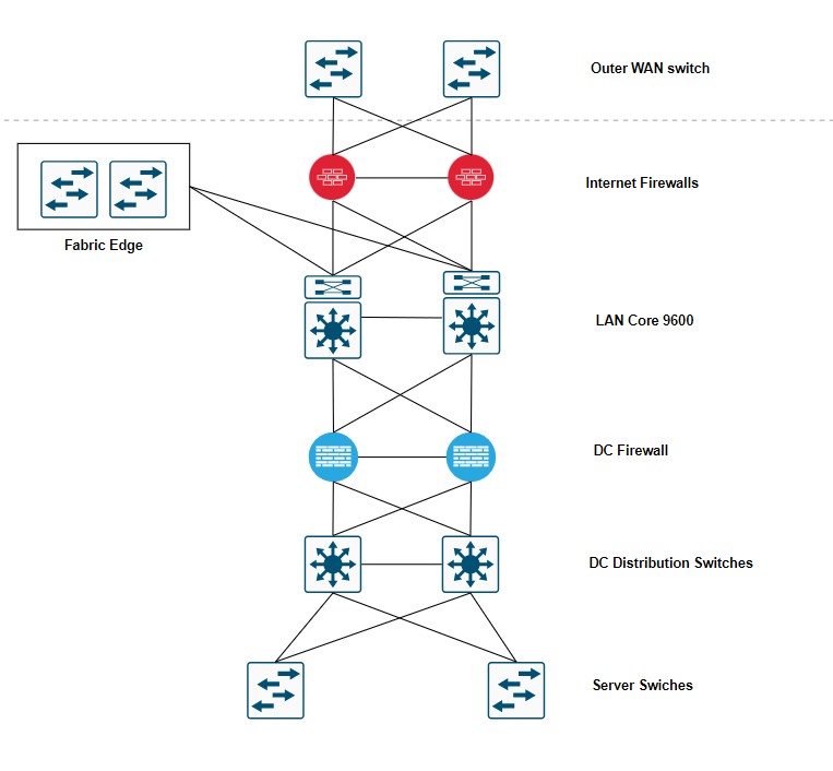
2- I have drawn up diagram to better explain the proposed network design. Please feel free to add your valuable inputs and recommendations.
3- For routing internet traffic routes through the Internet Edge firewall and DC traffic routes through the DC firewall. Do we need setup two separate BGP peering—one with the Internet Edge firewall for internet-bound traffic and another with the DC firewall for data center-bound traffic? How would be VN/VRF setup here?
- Mark as New
- Bookmark
- Subscribe
- Mute
- Subscribe to RSS Feed
- Permalink
- Report Inappropriate Content
10-30-2024 12:50 PM
1. I'd avoid consolidation of BN|CPs into Stackwise (unless it's FIAB but it's not your case afaiu). Some accounts still consolidate BN|CPs into VSL which make it more reliable than Stackwise. In this particular case VSL would fit better than others.
2. with Pub/Sub enabled it will be configured automatically in a single VPNV4 peering (no VRF Option A peering)
3. Keeping in mind that Active FW will be single point for eBGP peering with BN|CP layer, VSL'ed BN|CP will better fit here as there is single session is needed. Also BGP in case of FW failover will have better convergence. In case of separated BN|CPs u'll have 2 options: a) peering in the same transit VLAN (per VRF); b) peering in 2 different transit VLANs (per VRF) . In last case u'll need to configure 2xINSIDEs in the single Zone on the FW.
4. basically it doesnt look like you have better options here :0)
5. I'd say WLC must be fabric enabled. U never connect it to BNs but outside the Fabric.
- Mark as New
- Bookmark
- Subscribe
- Mute
- Subscribe to RSS Feed
- Permalink
- Report Inappropriate Content
10-30-2024 01:28 PM
Thank you @Andrii Oliinyk
Some accounts still consolidate BN|CPs into VSL which make it more reliable than Stackwise. In this particular case VSL would fit better than others.
Here you mean VSS. I second this, VSS would be much better to avoid create lot of BGP peerings. But VSS could be problamtic for maintenance window on software upgrade. BN/CP will be unavailable
with Pub/Sub enabled it will be configured automatically in a single VPNV4 peering (no VRF Option A peering)
I couldn't get this, could you please clarify more
basically it doesnt look like you have better options here :0)
But is it advisable or standard practice to make seperate bgp peering with each firewalls Internet Edge and DC, if the customer two seperate firewall deployments
I'd say WLC must be fabric enabled. U never connect it to BNs but outside the Fabric.
In both cases Fabric enabled and non fabric enabled, where would WLC connect on the network
- Mark as New
- Bookmark
- Subscribe
- Mute
- Subscribe to RSS Feed
- Permalink
- Report Inappropriate Content
11-02-2024 04:26 AM
VSL vs Separated BN|CPs: it's up to u to decide looking on all cons&pros
VRF OptionA: is essentially peering in arbitrary VRF: address-family ipv4 vrf CAPMUS. that is what BN|CPs are doing toward FNs.
between itselves they are peering in address-family vpnv4. with this they exchange VPNV4 NLRIs for each their VRFs in single peering.
peering with FNs of different kind: CVD recommends to use separate BN-layers to peer with Internal entities & Internet (Internal BN & External BN). if u want to stay with single BN-layer u need to use Anywhere BN.
WLC location: u may use eWLC on the your BN|CPs. it will work both for VSL'ed & separate nodes. but with separate nodes your Wireless redundancy will base on primary & secondary WLS instead of HA SSO with VSL.
- Mark as New
- Bookmark
- Subscribe
- Mute
- Subscribe to RSS Feed
- Permalink
- Report Inappropriate Content
11-02-2024 03:58 AM
Appreciate any further suggestions @Andrii Oliinyk @balaji.bandi
- Mark as New
- Bookmark
- Subscribe
- Mute
- Subscribe to RSS Feed
- Permalink
- Report Inappropriate Content
11-02-2024 05:38 AM
In case of separated BN|CPs u'll have 2 options: a) peering in the same transit VLAN (per VRF); b) peering in 2 different transit VLANs (per VRF) . In last case u'll need to configure 2xINSIDEs in the single Zone on the FW.
For option B, do we need a dedicated L2 switch between firewalls and BN/CP?
- Mark as New
- Bookmark
- Subscribe
- Mute
- Subscribe to RSS Feed
- Permalink
- Report Inappropriate Content
11-02-2024 06:38 AM
no. u just connect each FW-unit to BN|CP1 & BN|CP2 with separate phy link. on both side it has to be interface with .1Q encap (l.s. VLAN 300-302 for peering with FW from BN|CP1 in 3 different VRFs & VLAN 310-312 for peering with FW from BN|CP2 in same 3 VRFs).
then u create sessions between FW (manually) & BN|CPs (L3-handoff workflows).
stuff u also have to consider (on the example of ASA https://www.cisco.com/c/en/us/support/docs/security/asa-5500-x-series-next-generation-firewalls/118050-config-bgp-00.html#:~:text=individual%20routing%20protocols.-,BGP%20and%20Failover,-BGP%20is%20supported )
- Mark as New
- Bookmark
- Subscribe
- Mute
- Subscribe to RSS Feed
- Permalink
- Report Inappropriate Content
11-02-2024 07:32 AM
I updated the diagram. Given that, two separate borders, both border nodes would have separate, active BGP peerings with the Internet Edge and Data Center firewalls. Each border can independently route traffic to and from these firewalls. Advertise a default route to the fusion firewalls from the internet firewalls.
Appreciate your valuable input
- Mark as New
- Bookmark
- Subscribe
- Mute
- Subscribe to RSS Feed
- Permalink
- Report Inappropriate Content
11-02-2024 07:55 AM
looks simple as diagrams from CVD :0)
1. there is also routed IS-IS link between BN|CPs which is used for IBGP peering in VPNv4 AF.
2. be encouraged to review all your Internet access use-cases to properly address it with that simple diagram
- Mark as New
- Bookmark
- Subscribe
- Mute
- Subscribe to RSS Feed
- Permalink
- Report Inappropriate Content
11-02-2024 09:00 AM
Why do we need iBGP between the borders as there will be no traffic passing on that link? Links from each border to the fusion is fine.
Fabric edge will have LISP sessions with both BN/CP kind of load balancing fashion.
Both borders having BGP peering with Fusion so again both BNs/CPs will load balance to Fusion as well.
- Mark as New
- Bookmark
- Subscribe
- Mute
- Subscribe to RSS Feed
- Permalink
- Report Inappropriate Content
11-02-2024 09:07 AM
- Mark as New
- Bookmark
- Subscribe
- Mute
- Subscribe to RSS Feed
- Permalink
- Report Inappropriate Content
11-03-2024 11:38 AM
For border redundancy we will use the LISP Pub/Sub when configuring them as BN/CP, this should allow for a dynamic default border setup.
I have updated network diagram.
We’ll also be setting up two physical links between the border nodes My question is:
- Do these inter-border links need manual configuration, or will Cisco DNA Center automatically push and configure these links as part of the LISP Pub/Sub setup?
- WLC will be fabric enabled. Can we connect WLC to upstream switches in Data center space (Nexus switches) as shown in diagram but there is a firewall in between BNs and Nexus Switches
Appreciate your help
- Mark as New
- Bookmark
- Subscribe
- Mute
- Subscribe to RSS Feed
- Permalink
- Report Inappropriate Content
11-04-2024 12:35 AM - edited 11-04-2024 12:38 AM
Inter BN|CP link: it's stated to be configured automatically with PubSub: https://community.cisco.com/t5/software-defined-access-sd-access/sd-access-border-nodes-interconnection-design/td-p/5137340#:~:text=If%20the%20Fabric%20Site%20is%20Pub/Sub%20then%20there%27s%20no%20need%20for%20manual%20per%2DVRF%20IBGP%20between%20B... . But i observe Cisco CX prefers to configure it manually as part of prestaging before migrations in brown fields... i didnt try automation of this subject.
WLC: if u have solid reasons to avoid Primary/Secondary eWLC deployment on BN|CPs u can do it as soon as RTTs etc stuff is compliant to SDA requirements. i'm sure u wont forget to open CAPWAP & LISP on the FW for APs-WLC & CP-WLC interfactions.
Discover and save your favorite ideas. Come back to expert answers, step-by-step guides, recent topics, and more.
New here? Get started with these tips. How to use Community New member guide