- Cisco Community
- Technology and Support
- Networking
- Switching
- PIM needs to enabled on all
- Subscribe to RSS Feed
- Mark Topic as New
- Mark Topic as Read
- Float this Topic for Current User
- Bookmark
- Subscribe
- Mute
- Printer Friendly Page
Basic multicast configuration for a Layer3 Segmented network
- Mark as New
- Bookmark
- Subscribe
- Mute
- Subscribe to RSS Feed
- Permalink
- Report Inappropriate Content
10-09-2015 02:04 PM - edited 03-08-2019 02:09 AM
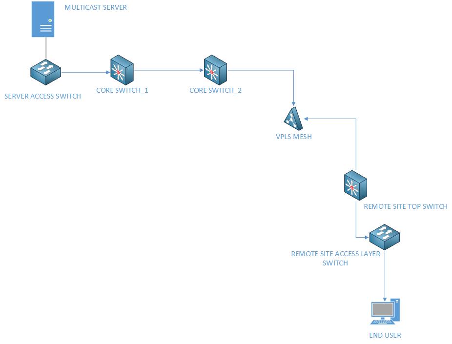
Pictured above is a very simple representation of the network as it stands today. We have recently added the VPLS Mesh via charter to connect our remote sites, and allow them to pass tagged traffic across, with the goal of segmenting each site into VLAN's, and allowing their respective top switches to act as the default gateway. All of that has been accomplished, however we are now having issues with multicast regarding streams from one of our servers to end devices in these newly converted sites. Sites that are still on the old Layer 2 segments are working. I've been poring over documentation on how to accomplish this, but haven't come up with a clear answer, and it's still not working. I'd be happy to tweak it later to fine tune its operation, but right now I'm looking for some help on basic connectivity given the current network topology.
So far:
-I have enabled IGMP snooping on all the switches pictured in the drawing, including IGMP on the individual VLAN's that are affected and the VLAN's that are passing traffic across the VPLS (Wasn't sure if that was necessary or not)
-I have enabled PIM-DM on the two core switches and the top switch of the remote site.
Still nothing. Any help would be greatly appreciated.
- Labels:
-
Other Switching
- Mark as New
- Bookmark
- Subscribe
- Mute
- Subscribe to RSS Feed
- Permalink
- Report Inappropriate Content
10-09-2015 05:37 PM
Hi,
Where is the gateway for the remote site users? Is it on the remote top switch?
Where is the Rendezvous Point for the network? Is it on core 1 and core 2?
Thanks
John
- Mark as New
- Bookmark
- Subscribe
- Mute
- Subscribe to RSS Feed
- Permalink
- Report Inappropriate Content
10-09-2015 07:52 PM
The default gateway for all VLAN's at the remote site are on the top switch at that site. From there, routes are distributed throughout the network via OSPF, and the CORE SWITCH_1 device propagates a default route down through the devices via OSPF. I'm not sure what you mean by "Rendezvous Point".
- Mark as New
- Bookmark
- Subscribe
- Mute
- Subscribe to RSS Feed
- Permalink
- Report Inappropriate Content
10-10-2015 08:31 AM
Some things to check -
1) you have enabled "ip multicast-routing" on all L3 devices in the path
2) it's not clear how the link is configured between the L3 switches ie. is it vlan with an SVI at either end or a L3 routed port configuration.
Either way you need to make sure you have enabled PIM on all the L3 interfaces in the path not just the server and client vlans
3) make sure the TTL of the multicast packets is greater than the number of L3 hops between server and client which is a setting within the multicast application.
If you have done all of the above then when the server is transmitting the stream and the client is trying to receive it can you post -
"sh ip mroute" from all L3 switches indicating which switch and what the group address is.
Jon
- Mark as New
- Bookmark
- Subscribe
- Mute
- Subscribe to RSS Feed
- Permalink
- Report Inappropriate Content
10-10-2015 09:24 AM
ip multicast-routing was enabled on all L3 devices between the server and the end user.
Over the VPLS Charter mesh, the two L3 devices use a SVI to connect to each other. Between the two core switches is simply a L3 link. PIM DM was enabled on all devices, but I'm unsure which links/VLAN's it needs to be enabled on.
- Mark as New
- Bookmark
- Subscribe
- Mute
- Subscribe to RSS Feed
- Permalink
- Report Inappropriate Content
10-10-2015 11:15 AM
PIM needs to enabled on all L3 interfaces in the path ie.
the server SVI, the L3 routed ports on both core switches, the SVI for the VPLS link on core switch 2, the SVI for the VPLS link on the remote switch and the SVI for the client vlan.
Edit - I'm assuming both access switches in your diagram are L2 and not L3.
Jon
Discover and save your favorite ideas. Come back to expert answers, step-by-step guides, recent topics, and more.
New here? Get started with these tips. How to use Community New member guide