- Cisco Community
- Technology and Support
- Networking
- Switching
- Express Setup Cisco Change
- Subscribe to RSS Feed
- Mark Topic as New
- Mark Topic as Read
- Float this Topic for Current User
- Bookmark
- Subscribe
- Mute
- Printer Friendly Page
Express Setup Cisco Change
- Mark as New
- Bookmark
- Subscribe
- Mute
- Subscribe to RSS Feed
- Permalink
- Report Inappropriate Content
10-17-2017 08:20 AM - edited 03-08-2019 12:23 PM
Hello,
My english is not good...sorry i m french :)
If you use Express Setup , IP adress not 10.0.0.1, but 192.168.1.1 to join express setup
And you have new interface, with new username and password (i don t find documentation :-()
Somebody can help me ?
thanks you
- Labels:
-
Other Switching
")
")
- Mark as New
- Bookmark
- Subscribe
- Mute
- Subscribe to RSS Feed
- Permalink
- Report Inappropriate Content
10-17-2017 08:48 AM
Hi
here is the documentation for express setup on 3650 model
Use Express Setup to enter the initial IP information. This action enables the switch to connect to local routers and the Internet. You can access the switch through the IP address for further configuration.

Note ![]() To use the CLI-based initial setup program, see Appendix C, "Configuring the Switch with the CLI-Based Setup Program," in the Catalyst 3650 Switch Hardware Installation Guide.
To use the CLI-based initial setup program, see Appendix C, "Configuring the Switch with the CLI-Based Setup Program," in the Catalyst 3650 Switch Hardware Installation Guide.
You need this equipment:
•![]() PC or laptop with Windows Vista, XP, or 7
PC or laptop with Windows Vista, XP, or 7
•![]() Browser (Internet Explorer 5.5, 6.0, or 7.0, or Firefox 1.5, 2.0, or 3.0) with JavaScript enabled
Browser (Internet Explorer 5.5, 6.0, or 7.0, or Firefox 1.5, 2.0, or 3.0) with JavaScript enabled
•![]() Straight-through or crossover Category 5 Ethernet cable
Straight-through or crossover Category 5 Ethernet cable
Note ![]() Before running Express Setup, disable any pop-up blockers or proxy settings in your browser and any wireless client running on your PC or laptop.
Before running Express Setup, disable any pop-up blockers or proxy settings in your browser and any wireless client running on your PC or laptop.
|
Step 1 |
Make sure that nothing is connected to the switch. |
|
|
Step 2 |
During Express Setup, the switch acts as a DHCP server. If your PC or laptop has a static IP address, temporarily change your PC or laptop settings before you use DHCP. Note |
|
|
Step 3 |
Install the power supply modules. See the "Power Supply Installation" chapter in the Catalyst 3650 Switch Hardware Installation Guide for instructions. http://www.cisco.com/go/cat3650_hw Note |
|
|
Step 4 |
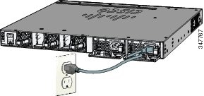
Power the switch. AC power switches: Plug the AC power cord into the switch power supply and into a grounded AC outlet. DC power switches: See the wiring instructions in the Catalyst 3650 Switch Hardware Installation Guide on Cisco.com: |
|
|
Step 5 |
Observe the POST results. Approximately 30 seconds after the switch powers on, it begins the power-on self-test (POST), which can take up to 5 minutes to complete. During POST, the SYSTEM LED blinks green. When POST is complete, the SYSTEM LED turns solid green. The ACTV LED is green if the switch is acting as the active switch. Note Troubleshooting: If the SYST LED does not turn solid green, or turns amber, the switch failed the POST. Contact your Cisco representative or reseller. |
|
|
Step 6 |
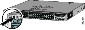
Press and hold the Mode button until all the LEDs next to the Mode button turn green. You might need to hold the button for more than 3 seconds. The switch is now in Express Setup mode. Troubleshooting: If the LEDs next to the Mode button blink when you press the button, release it. Blinking LEDs mean that the switch is already configured and cannot go into Express Setup mode. For more information, see the "Resetting the Switch" section. |
|
|
Step 7 |
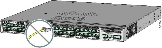
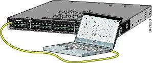
Connect a Category 5 Ethernet cable to a port: • • Connect the other end of the cable to the Ethernet port on your PC or laptop. Wait until the port LEDs on the switch and your PC or laptop are green or blinking green. Green LEDs indicate a successful connection. Troubleshooting: If the port LEDs do not turn green after about 30 seconds, make sure that: • • • |
|
|
Step 8 |
Start a browser session on the PC or laptop, and enter the IP address https://10.0.0.1. When prompted, enter the default password, cisco. Note The Express Setup window appears. Troubleshooting: If the Express Setup window does not appear, make sure that any browser pop-up blockers or proxy settings are disabled and that any wireless client is disabled on your PC or laptop. |
|
|
Step 9 |
Enter this information in the Network Settings fields: Note • Note • • • • Note (Optional) Enter this information in the Ethernet Management Port Settings fields: • |
|
|
Step 10 |
(Optional) You can enter other administrative settings in the Optional Settings fields. You can enter the Optional Settings information now or enter it later using the Device Manager interface. For example, the optional administrative settings identify and synchronize the switch for enhanced management. NTP automatically synchronizes the switch clock with the network clock. You can manually set the system clock if the switch should have different settings. |
|
|
Step 11 |
(Optional) You can select the Advanced Settings tab on the Express Setup window and enter the advanced settings now or enter them later using the Device Manager interface.
• • • • • • Note |
|
|
Step 12 |
Click Submit to save your changes and to complete the initial setup. After you click Submit: • • For more information about Express Setup fields, see the online help for the Express Setup window. |
|
|
Step 13 |
Disconnect the switch from the PC and laptop, and install the switch in your network. See the "Installing the Switch" section. |
|
|
Step 14 |
If you changed the static IP address on your PC or laptop in Step 2, change it to the previously configured static IP address. |
|
|
Step 15 |
See the "Managing the Switch" section for information about configuring and managing the switch. |
|
- Mark as New
- Bookmark
- Subscribe
- Mute
- Subscribe to RSS Feed
- Permalink
- Report Inappropriate Content
10-20-2017 07:33 AM
- Mark as New
- Bookmark
- Subscribe
- Mute
- Subscribe to RSS Feed
- Permalink
- Report Inappropriate Content
10-20-2017 07:37 AM - edited 10-20-2017 07:39 AM
You can do a password recovery and configure it through cli that way reset it to default , 192 is not a default ip that's used it looks as if its being reconfigured by someone else , Cisco only use admin/cisco or cisco/cisco as there default logins , so another password has been setup on it
- Mark as New
- Bookmark
- Subscribe
- Mute
- Subscribe to RSS Feed
- Permalink
- Report Inappropriate Content
10-01-2018 02:45 PM
The Cisco documentation for the WS-C3650 switches is incorrect.
You'll need to utilize a console cable and connect to the switch through the management port on the back of the switch to setup the initial configuration.
Once you connect you, may see a black telnet/putty window. Pressing the Enter key will show a message stating: "Would you like to enter the initial configuration dialog? [yes/no]:"
Type yes and press enter. Follow the prompts.
Hope this helps. Good luck!
Discover and save your favorite ideas. Come back to expert answers, step-by-step guides, recent topics, and more.
New here? Get started with these tips. How to use Community New member guide