- Cisco Community
- Technology and Support
- Networking
- Switching
- Secure network on Cisco Packet Tracer
- Subscribe to RSS Feed
- Mark Topic as New
- Mark Topic as Read
- Float this Topic for Current User
- Bookmark
- Subscribe
- Mute
- Printer Friendly Page
Secure network on Cisco Packet Tracer
- Mark as New
- Bookmark
- Subscribe
- Mute
- Subscribe to RSS Feed
- Permalink
- Report Inappropriate Content
04-08-2020 07:54 AM
Right, I am pretty new to networking and I got this assignment where there are 3 existing departmental teams that will be relocating to the new building. An IT team, a Marketing team and a HR team.
There are 3 floors within the building which will be utilised. The new building can service up to 30 members of staff, who will be evenly allocated across the 3 floors, however each floor contains a mixed number of personnel from each team. Certain network assets will be placed within the building, including servers and security controls. Staff from certain teams need to be able to access particular assets and some will need to be able to remotely access those assets in a secure manner (see below).
In addition, clients may be visiting the building and a guest wireless access point must be provided.
- Use DHCP, Classes and Subnetting where appropriate
- You will need to implement Virtual Local Area Networks (VLANs) that place each team within the same VLAN segment and allows them to communicate with each of their own team’s members and designated network assets, regardless of physical location (i.e. floor number).
- The VLAN should be secured so that only the originating department has access on that VLAN with the exception of the IT service team which has access across all 3
- Discuss the logical IP addressing of each floor / VLAN
- The network should be segmented and you must include a De-militarized Zone (DMZ) where appropriate
- Include any additional security features and redundancy measures to reduce any single points of failure
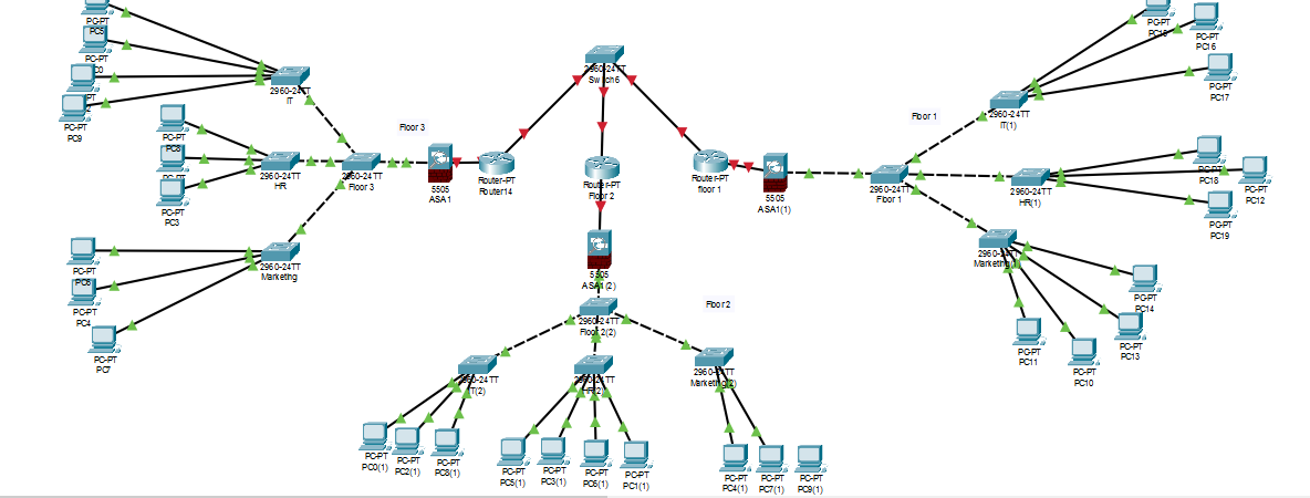
My question is, how can I make this thing work? I have uploaded the pkt file and a screenshot where I have already made a start on it.
- Mark as New
- Bookmark
- Subscribe
- Mute
- Subscribe to RSS Feed
- Permalink
- Report Inappropriate Content
04-08-2020 09:00 AM
Hello,
that is a rather large project. What part are you having trouble with exactly ? Is the IP addressing arbitrary, or have you been given device IP addresses and subnets (and Vlan numbers) ?
- Mark as New
- Bookmark
- Subscribe
- Mute
- Subscribe to RSS Feed
- Permalink
- Report Inappropriate Content
04-08-2020 10:37 AM
I am stuck on the whole thing
- Mark as New
- Bookmark
- Subscribe
- Mute
- Subscribe to RSS Feed
- Permalink
- Report Inappropriate Content
04-08-2020 09:30 AM
The first thing I would recommend is get a plan together; where are the services going to be hosted and all of that fun stuff. I see the server objects at the top, but are you going to use them? Where are you putting them? Stuff like that.
I see three sites, but the objective doesn't state that is necessary. I bring it up because there is an easy way and a more complicated way to do this depending on the number of connections. By this I mean simply you will either need to run VPN off the ASA or the Routers, the former being far easier. The ASA series firewalls have difficulty with routing over Site-to-Site to multiple sites (that is, past 2). This would almost mandate you using the routers for VPN tunneling over the internet.
I would replace Switch 6 with a Router and call it "Internet". It's been a very long time since I played with Packet Tracer, but if you cannot do this with a router (port count restrictions), put a Multi-layered Switch in there. You could use a protocol if you wish, but there wouldn't be a need unless you do VRF (if you want to actually simulate the internet, go nuts with that). As it stands now, you cannot get that switch to do this as it will not be routing, requiring all "external" links to be in the same network, which simply cannot realistically happen.
I would then get each site functional independently and capable of pinging the "inside" interface of "Internet" for each segment. From there, determine where resources are going (where is your DMZ going?) and make sure that functions correctly. Then, create the VPN tunnel(s) between the sites and set the traffic.
I'm not attaching configurations (yet) because I'm not sure if you are trying a proof-of-concept for work (in which I'll happily assist) or you're attempting to learn a great deal of networking at once for a class (in which if you get really specific I can assist along the way). Also, I come back to the number of site concerns; if you want some configuration guidance for novice-to-intermediate knowledge levels then make it a two-site configuration. If you want to start down the road of mGRE, DMVPN or some other star-topology VPN technology then this is going to take some serious time and discussion.
- Mark as New
- Bookmark
- Subscribe
- Mute
- Subscribe to RSS Feed
- Permalink
- Report Inappropriate Content
04-08-2020 09:44 AM
Wow, ok, I can now see it clearer that I downloaded packet tracer.
So, first thing I would do is not what you did. Each of those routers is a floor eh? That's not realistic at all. Same with separating all of the department on their own switch. Let's not do that. I'm going to upload a different topology to start with. Give me a second.
- Mark as New
- Bookmark
- Subscribe
- Mute
- Subscribe to RSS Feed
- Permalink
- Report Inappropriate Content
04-08-2020 09:54 AM
Please! That would be extremely helpful!
- Mark as New
- Bookmark
- Subscribe
- Mute
- Subscribe to RSS Feed
- Permalink
- Report Inappropriate Content
04-08-2020 10:19 AM
So, this would be a typical (using the term very loosely) for this kind of situation. Nothing is configured yet, I just wanted to give you an idea of the difference. I may change the switches to be a bit more realistic, as I was going for POE for the access points (the wireless requirement) but I can't figure out how to get the controllers to configure in this thing (I'm very familiar with WLC... this just isn't giving me the option ... also, in a "guest" type environment for wireless you would typically anchor in the DMZ... if I can't get to the GUI this isn't going to be very realistic at all...).
I'll throw some config on it here in a moment to give you some more insight.
- Mark as New
- Bookmark
- Subscribe
- Mute
- Subscribe to RSS Feed
- Permalink
- Report Inappropriate Content
04-08-2020 10:36 AM
- Mark as New
- Bookmark
- Subscribe
- Mute
- Subscribe to RSS Feed
- Permalink
- Report Inappropriate Content
04-08-2020 10:47 AM
Hi sir, what version of packet tracer r u using? ?I'm using 7.1.1
- Mark as New
- Bookmark
- Subscribe
- Mute
- Subscribe to RSS Feed
- Permalink
- Report Inappropriate Content
04-08-2020 10:59 AM
For Packet Tracer, it's 7.3.0.
Here's the updated topology with some config. And, now, a rundown on the changes:
First, the DHCP server was added with a few scopes. As a general practice, I do not create a DHCP scope for Servers (this irritates some server admins that try to automate without the proper tools, but hey, I'm the network guy and they can hate me), but I did create one for HR, IT and Marketing. Here's how I broke up the VLANs:
VLAN0010 = IT
VLAN0020 = HR
VLAN0030 = MARKETING
VLAN0040 = INTERNAL_SERVERS
VLAN0999 = MANAGEMENT
The first three make sense, I broke out the Internal servers into their own VLAN as these will be servers used by all VLAN such as DHCP and DNS. The management VLAN is my OCD... never, ever use VLAN0001 as a native. Ever. Even in demos.
Next, I have the aggregation switch in the center of it all. This will be the "router" for internal networking. Why? It's easier, and typically you'll see this in an installation. You could use the firewall, but there isn't really a need for internal workings. Use a management system like ISE and DNA to keep internal traffic safe from internal traffic, but for this example I'm trusting a great deal of security to the access lists I'll add next. So on the aggregation switch I have the VLAN's with the gateway addresses. This is what will forward the DHCP requests (kind of) to the server. The IP helper-address commands on VLAN 10, 20 and 30 are necessary for DHCP to work correctly. Why? Well, a terrible explanation of DHCP is necessary: it uses broadcasts and VLANs separate broadcast domains. So, if I broadcast in VLAN 10, there isn't going to be a response (no DHCP server in VLAN 10). I have to direct the broadcast to the unicast address of someone who will respond; in this case it's 192.168.40.2.
I then trunked the 3 switches on the floors to the Aggregation switch, as well as the Datacenter switch. My OCD then kicked in again and I "pruned" the trunks to only allow the VLANS that are utilizing these switches, so you'll see the command "switchport trunk allowed vlan 10,20,30,40,999" on each trunk. Not necessary but good practice.
So, you can test the DHCP communication (and the communication between all VLANs at this point) by moving the ports connected to the PC to a different VLAN grouping (or changing the vlan on the port they are already connected). I did this for all switches on the floors:
Ports 1/0/1 - 8 : VLAN 0010
Ports 1/0/9 - 16: VLAN 0020
Ports 1/0/10 - 23 VLAN 0030
Next, I'll do the ACL for the VLANs between each other and post that change.
- Mark as New
- Bookmark
- Subscribe
- Mute
- Subscribe to RSS Feed
- Permalink
- Report Inappropriate Content
04-08-2020 11:30 AM
Here we go:
The Access-lists VLAN0020_EGRESS and VLAN0030_EGRESS were added, and the commands issued for the appropriate VLANS. This filters the correct paths as follows:
VLAN0020 clients cannot communicate with VLAN0030 clients.
VLAN0030 clients cannot communicate with VLAN0020 clients.
VLAN0010 clients can communicate with VLAN0020 clients.
VLAN0020 clients can communicate with VLAN0010 clients.
VLAN0010 clients can communicate with VLAN0030 clients.
VLAN0030 clients can communicate with VLAN0010 clients.
ALL can communicate with VLAN0040 clients/servers.
To show, I added two dummy servers to the Datacenter switch, one in VLAN0020 and the other in VLAN0030. The IP addresses are 192.168.20.201 (VLAN0020) and 192.168.30.201 (VLAN0030). All hosts can hit their respective server, but not the other. All hosts can hit the DHCP server (VLAN0040) without issue.
The management VLANs for the switches were given IP addresses so they can find the other networks.
I guess I should tell you the IP scheme now:
VLAN0010 = 192.168.10.0/24, Gateway 192.168.10.1
VLAN0020 = 192.168.20.0/24, Gateway 192.168.20.1
VLAN0030 = 192.168.30.0/24, Gateway 192.168.30.1
VLAN0040 = 192.168.40.0/24, Gateway 192.168.40.1
VLAN0999 = 10.1.1.0/24, Gateway 10.1.1.200 (yeah, I just wanted to be different here)
So, this will bring us to the DMZ, followed by the wireless and you're square.
Do me a favor: do not implement this in production. While this will work, there are a lot of liberties going on with some security practices. While this is more secure than a lot of networks I have seen (just given the fact that it isn't flat in VLAN, that there are actually access control lists, and VLAN pruning happened), I try to steer people away from using things are not up to my standards of "at least a little bit secure".
- Mark as New
- Bookmark
- Subscribe
- Mute
- Subscribe to RSS Feed
- Permalink
- Report Inappropriate Content
04-08-2020 11:57 AM
Alright, I lied. Here's the deal: Packet Tracer is not really conducive to operating in this capacity. I cannot configure the ASA at all, and the AIR-2504/3504 doesn't configure well either.
So, I'll walk you through the "real-world" solution at the end of this, just so you can have an answer to your question.
DMZ Requirement:
I'm going to assume this is a budget-constrained implementation, or at least a low-level implementation, because believe me there is a MUCH deeper dive we can go into with APC, APIC, ISE, DNS, FirePower, ESA, WSA, CSA, and blah, blah, blah. We'll go old-school, 4-tuple firewall without intent-based networking (though, I suppose you could use faux implements of Class-of-Service on the ISR and Zone-based Firewalling, but this is ....meh, in comparison).
With the outline I gave you, you'd have 2 ASA5506. These are routed firewalls, and would require some networking. We'll change that to one ASA5506 (you'd go bigger if this was a larger implementation) and one FP2110 (NGFW). Reason being is this: passthrough connections that filter threats and malware should be placed close to your internal network, and this should filter out anything but database calls to the appropriate servers from the appropriate servers. Simple enough to do with a FP2110, expensive (both monetarily and CPU) with a ASA.
On the ASA you would create another VLAN on a subinterface and route through to the aggregation switch. I would recommend a IGRP on the Aggregation router with authentication, but static works just as well. Create another subinterface on another interface for the wireless controller (next section) and give it a different VLAN. Make sure that routes to the Aggregation switch as well. Secure these in this manner:
Internal networks should communicate with the application server ONLY.
Application servers (the DMZ servers) should communicate back ONLY on web ports.
Application servers should only communicate unsolicited to database or data repositories. I prefer not profiling this, and explicitly defining the rules (severe downside to this is human error... i make a lot of them).
Wireless Controller B (in the DMZ) should only communicate to Wireless Controller A (in Data Center) over UDP ports 16666 and 16667. That is all that is required to anchor (I think... now that one has been a while... double-check that).
Wireless Guest Access Requirement:
Alright, all access points will be manged by Wireless Controller A. You'll need to create a DHCP pool for Wireless management interfaces for the Managed Access Points (don't call them "WAPs"... this means at least 3 other things in networking...). This pool will require a DHCP option that points to the wireless controller's management IP address for association. This is a bit advanced in concept; just know it has to be done and done so in a manner that utilizes Hex formatting of addressing. Then, Wireless Controller B will be configured with a management IP address (should be another network) and that address will be allowed through the firewalls and routed in a way that it can see Wireless Controller A and vice versa. Then the bridge will be configured. This encapsulates all wireless traffic in the anchored bridge to go straight to that device and not anywhere else (secure).
That's all you need!
As a quick note, I totally messed up the DMZ in the diagrams. The internal ASA should not be connected to the switch; only the switch should hook up to the ASA closest to the router only. This will force all traffic going inside to hope through both firewalls, where the perimeter firewall will be "less strict" than the one closest to the internal network. That was just a bad, bad connection I did.
Hope this helps. I'm stepping away for a bit, as I just got a notification that one of my sites is seeing some serious noise that appears to be an attack and I am now "essential" and must travel.... Yay. Good luck with Networking!
- Mark as New
- Bookmark
- Subscribe
- Mute
- Subscribe to RSS Feed
- Permalink
- Report Inappropriate Content
04-08-2020 12:18 PM
Thank you for your efforts! Appreciate it
- Mark as New
- Bookmark
- Subscribe
- Mute
- Subscribe to RSS Feed
- Permalink
- Report Inappropriate Content
04-09-2020 04:54 AM
Discover and save your favorite ideas. Come back to expert answers, step-by-step guides, recent topics, and more.
New here? Get started with these tips. How to use Community New member guide