Hi, Everyone
I have been working in Network Design and I came across Cisco Live Document titled " Advanced Enterprise Campus Design Routed Access (2013 Orlando) " and I stopped at the slide where it mentioned "What Area Should the Distribution Link Be In?" and within that slide it is recommended to "Configure dist to dist link as a trunk using 2 subnets, one in area 0 and one in stub area when possible".
Well, I draw one Diagram of typical Core-Distribution-Access with three possible ways that the Distribution interconnection be configured with (see picture below):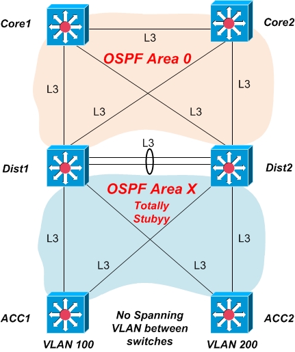
- 1. Layer 3 Dist. Interconnection in Area 0 : (see picture below)
- In case one of the access layer uplink failure, the return traffic from Dist2 (Note: Equal-cost path are considered here so both Dist1 & Dist2 are actively forwarding traffic) would follow sub-optimal path passing two-hops to get to the destination access switch (because ABR would prefer the Intra-Area route ACC2-Dist1-ACC1 over the Inter-Area route Dist1-ACC1 regardless of cost).
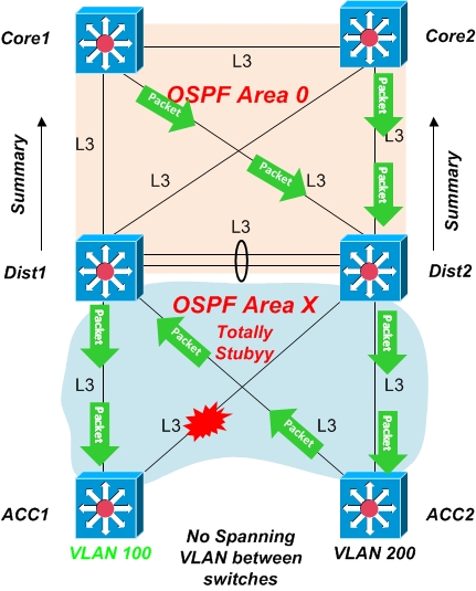
- 2. Layer 3 Dist. Interconnection in Area X : (see picture below)
- In case one of the access layer uplink failure, the return traffic from Dist2 (Note: Equal-cost path are considered here so both Dist1 & Dist2 are actively forwarding traffic) would follow Optimal path passing one-hops to get to the destination access switch (because ABR would prefer the Intra-Area route Dist1-ACC1 (lower cost )over the Intra-Area route ACC2-Dits1-ACC1 (Higher cost)).

- 3. Layer 2 Dist. Interconnection : (see picture below)
- Here the interconnection is L2 trunk with two Allowed VLANs:
- 1. Area 0 VLAN with Interface VLAN A in both distribution used to form OSPF adjacency.
- 2. Area X VLAN with Interface VLAN B in both distribution used to form OSPF adjacency.
- 3. Both VLAN A and VLAN B are allowed on the trunk.
- Here again In case one of the access layer uplink failure, the return traffic from Dist2 would follow Optimal path passing one-hops to get to the destination access switch (Same like previous case plus we have now Area 0 Continuity between Distribution switches through the interconnection link.

So first is it the last case what Cisco meant by “Configure dist to dist link as a trunk using 2 subnets, one in area 0 and one in stub area when possible" or they meant something else?
Second Why it is required as I can see putting the L3 Interconnection in non-backbone area has the same effect? I cannot see difference between second and last case except in case of multiple link failures?