- Cisco Community
- Technology and Support
- Data Center and Cloud
- Unified Computing System (UCS)
- Unified Computing System Knowledge Base
- Linux Bonding with Cisco VIC in Stand Alone Mode - RHEV Use Case
- Subscribe to RSS Feed
- Mark as New
- Mark as Read
- Bookmark
- Subscribe
- Printer Friendly Page
- Report Inappropriate Content
- Subscribe to RSS Feed
- Mark as New
- Mark as Read
- Bookmark
- Subscribe
- Printer Friendly Page
- Report Inappropriate Content
02-28-2016 04:46 PM - edited 03-01-2019 01:38 PM
One of the unappreciated features of the Cisco C-Series server is the ability to carve up the VIC into multiple virtual adapters. This allows you to apply things like jumbo frames and COS to adapters on the same physical link. It also makes dealing with trunked VLANs easier, eliminating the need to use VLAN interfaces in the OS.
In this document I am using a C220 M3 with a 1225 card for a Red Enterprise Virtualization Hypervisor host. This is an excellent example of the flexibility of the Cisco VIC because on a single 2 port card I need to support a management network, a storage network, and a Linux bridge for VM networks. I have also successfully used this feature of the VIC to create Ceph and SwiftStack servers with 4 10GBE ports and 4 way LACP bonds, with no issues. There is an example of a more complex setup in the linked CiMC CLI how-to below.
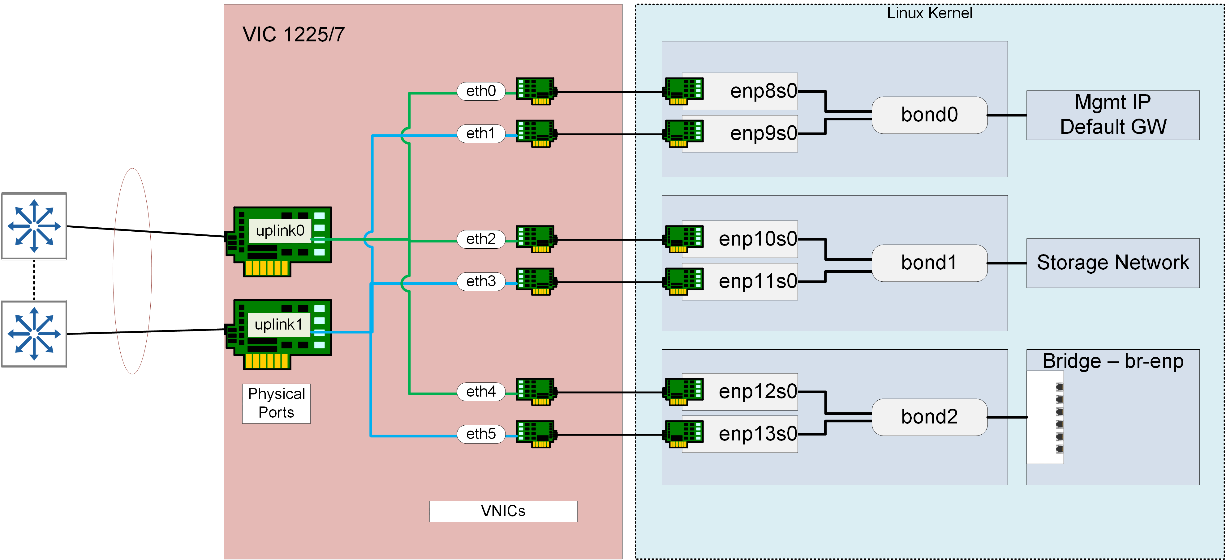
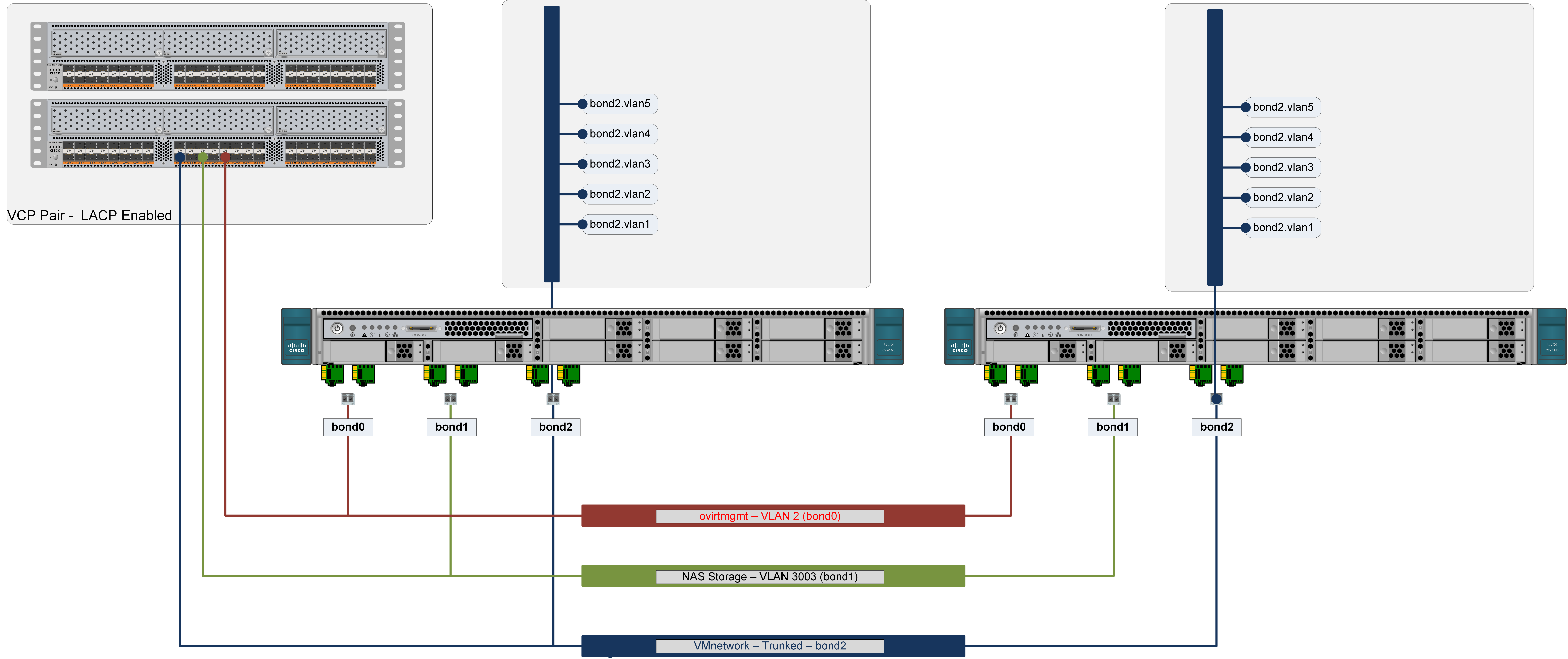
This is what we want the layout of the server to look like. There are 3 important layers, the L2 switches, the VIC, and the Linux kernel configuration. I will walk through each of these.

Exploded Server View:

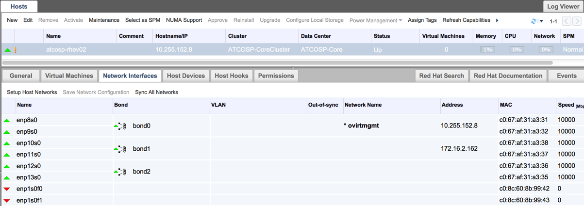
It will look like this in RHEV-M:

Related Documents:
- CIMC CLI Command Reference
- Basic NIC Bonding in RHEL
- Bootstrap Configuration for RHEL/Centos
- Configuring Port Channels [Cisco Nexus 5000 Series Switches…
*** Important bonding mode support information:
You should read and understand this KB Article from Red Hat, it is generally applicable to all Linux Distros.
https://access.redhat.com/solutions/67546
This is important to understand in the context of UCS. KVM with Linux bridge only supports LACP/802.3ad bonding mode for load distribution/balancing. The VIC in stand-alone mode fully supports LACP/802.3ad bonding mode for KVM, however, the VIC connected to Fabric Interconnects cannot be configured in 802.3ad bonds, only mode 5 and 6 - alb/tlb, which KVM does not support. Unfortunately OVS no longer supports alb/tlb either so if you are using VIC+UCS, you are stuck using active/passive failover bonds or Fabric Failover.
Nexus 5596 Port Channel Configuration
This is a standard 2 switch with VPC peer link configuration.
Switch-A:
ATCOSPN5KA# feature lacp
ATCOSPN5KA# show feature | grep lacp
lacp 1 enabled
ATCOSPN5KA# sho run int e1/36
!Command: show running-config interface Ethernet1/36
!Time: Fri Aug 12 20:52:02 2011
version 6.0(2)N2(5)
interface Ethernet1/36
description VPC Port-channel to RHEV-Host-2
switchport mode trunk
channel-group 32 mode active
ATCOSPN5KA# sho run int po 32
!Command: show running-config interface port-channel32
!Time: Fri Aug 12 20:52:17 2011
version 6.0(2)N2(5)
interface port-channel32
description To RHEV-Host-2
switchport mode trunk
vpc 32
Cisco VIC Configuration
It is much easier if you use the CIMC CLI for these activities rather than the GUI.
I created a CIMC CLI reference document which you can reference (CIMC CLI Command Reference )
Discover existing NIC configuration -
vietmeik@Skarn (~)$ ssh admin@10.255.152.95
admin@10.255.152.95's password:
C220-FCH1731V2GJ# scope chassis
C220-FCH1731V2GJ /chassis # sh adapter
PCI Slot Product Name Serial Number Product ID Vendor
-------- -------------- -------------- -------------- --------------------
1 UCS VIC 1225 FCH1731J48Y UCSC-PCIE-C... Cisco Systems Inc
NOTE - Depending on the server platform and VIC arrangement, MLOM vs PCI card for example the, Adapter number will be different.
C220-FCH1731V2GJ /chassis # scope adapter 1
C220-FCH1731V2GJ /chassis/adapter # show host-eth-if
Name MTU Uplink Port MAC Address CoS VLAN PXE Boot iSCSI Boot
---------------- ---- ----------- ----------------- --- ---- -------- ----------
eth0 1500 0 C0:67:AF:31:A3:31 0 2 disabled disabled
eth1 1500 1 C0:67:AF:31:A3:32 0 2 disabled disabled
eth5 1500 1 C0:67:AF:31:A3:35 0 NONE disabled disabled
eth4 1500 0 C0:67:AF:31:A3:36 0 NONE disabled disabled
eth3 9000 1 C0:67:AF:31:A3:37 0 3003 disabled disabled
eth2 9000 0 C0:67:AF:31:A3:38 0 3003 disabled disabled
These are the completed VNICs, I will walk through setting them up in the following steps. A note on this output - the VNICs are not listed in the PCI device order that you will see in the Linux kernel, nor are the MAC addresses allocated in order. This can be confusing later as you will see (A CDET is open to fix this).
Important things to note in this output, the VLAN assignment and MTU:
C220-FCH1731V2GJ /chassis/adapter # scope host-eth-if eth0
C220-FCH1731V2GJ /chassis/adapter/host-eth-if # sh detail
Name eth0:
MTU: 1500
Uplink Port: 0
MAC Address: C0:67:AF:31:A3:31
CoS: 0
Trust Host CoS: disabled
PCI Order: 0
VLAN: 2
VLAN Mode: TRUNK
Rate Limiting: OFF
PXE Boot: disabled
iSCSI Boot: disabled
Channel Number: N/A
Port Profile: N/A
Uplink Failover: N/A
Uplink Failback Timeout: N/A
These are some other interesting features available that could be useful but won't be investigated in this document:.
CoS: 0
Trust Host CoS: disabled
Rate Limiting: OFF
Rate Limiting:
An egress rate limiter which you can define the upper BW limit the vnic can have. Might be useful for chatty protocols or greedy workloads like VMotion.
CoS:
Ensure that the workloads are treated to the proper QOS SLA within the network. This is an outbound marking, from server to network. This is only useful when the QOS is properly set from source to destination.
Setup vNICs:
By default there will only be 2 vnics:
C220-FCH1731V2GJ /chassis # top
C220-FCH1731V2GJ /chassis # scope adapter 1
C220-FCH1731V2GJ /chassis/adapter # show host-eth-if
Name MTU Uplink Port MAC Address CoS VLAN PXE Boot iSCSI Boot
---------------- ---- ----------- ----------------- --- ---- -------- ----------
eth0 1500 0 C0:67:AF:31:A3:31 0 NONE disabled disabled
eth1 1500 1 C0:67:AF:31:A3:32 0 NONE disabled disabled
There are 2 steps -
- Configure existing NICS
- Add new NICS
Modify existing NICS:
C220-FCH1731V2GJ /chassis/adapter # scope host-eth-if eth0
C220-FCH1731V2GJ /chassis/adapter/host-eth-if # set order 0
C220-FCH1731V2GJ /chassis/adapter/host-eth-if *# set vlan 2
C220-FCH1731V2GJ /chassis/adapter/host-eth-if *# set vlan-mode trunk
C220-FCH1731V2GJ /chassis/adapter/host-eth-if *# commit
C220-FCH1731V2GJ /chassis/adapter/host-eth-if # exit
C220-FCH1731V2GJ /chassis/adapter # scope host-eth-if eth1
C220-FCH1731V2GJ /chassis/adapter/host-eth-if # set order 1
C220-FCH1731V2GJ /chassis/adapter/host-eth-if *# set vlan 2
C220-FCH1731V2GJ /chassis/adapter/host-eth-if *# set vlan-mode trunk
C220-FCH1731V2GJ /chassis/adapter/host-eth-if *# commit
C220-FCH1731V2GJ /chassis/adapter/host-eth-if *# exit
C220-FCH1731V2GJ /chassis/adapter/ *#
Add and modify new NICS:
Add:
C220-FCH1731V2GJ /chassis/adapter *# create host-eth-if eth2
C220-FCH1731V2GJ /chassis/adapter/host-eth-if *# exit
C220-FCH1731V2GJ /chassis/adapter *# create host-eth-if eth3
C220-FCH1731V2GJ /chassis/adapter/host-eth-if # exit
C220-FCH1731V2GJ /chassis/adapter *# create host-eth-if eth4
C220-FCH1731V2GJ /chassis/adapter/host-eth-if *# exit
C220-FCH1731V2GJ /chassis/adapter *# create host-eth-if eth5
C220-FCH1731V2GJ /chassis/adapter/host-eth-if *# exit
C220-FCH1731V2GJ /chassis/adapter *#
Modify:
C220-FCH1731V2GJ /chassis/adapter *# scope host-eth-if eth2
C220-FCH1731V2GJ /chassis/adapter/host-eth-if # set uplink 0
C220-FCH1731V2GJ /chassis/adapter/host-eth-if *# set order 2
C220-FCH1731V2GJ /chassis/adapter/host-eth-if *# set vlan 3003
C220-FCH1731V2GJ /chassis/adapter/host-eth-if *# set vlan-mode trunk
C220-FCH1731V2GJ /chassis/adapter/host-eth-if *# set boot disabled
C220-FCH1731V2GJ /chassis/adapter/host-eth-if *# set mtu 9000
C220-FCH1731V2GJ /chassis/adapter/host-eth-if *# exit
C220-FCH1731V2GJ /chassis/adapter *# scope host-eth-if eth3
C220-FCH1731V2GJ /chassis/adapter/host-eth-if *# set uplink 1
C220-FCH1731V2GJ /chassis/adapter/host-eth-if *# set order 3
C220-FCH1731V2GJ /chassis/adapter/host-eth-if *# set vlan 3003
C220-FCH1731V2GJ /chassis/adapter/host-eth-if *# set vlan-mode trunk
C220-FCH1731V2GJ /chassis/adapter/host-eth-if *# set boot disabled
C220-FCH1731V2GJ /chassis/adapter/host-eth-if *# set mtu 9000
C220-FCH1731V2GJ /chassis/adapter/host-eth-if *# exit
C220-FCH1731V2GJ /chassis/adapter # scope host-eth-if eth4
C220-FCH1731V2GJ /chassis/adapter/host-eth-if # set uplink 0
C220-FCH1731V2GJ /chassis/adapter/host-eth-if *# set order 4
C220-FCH1731V2GJ /chassis/adapter/host-eth-if *# set vlan-mode trunk
C220-FCH1731V2GJ /chassis/adapter/host-eth-if *# set boot disabled
C220-FCH1731V2GJ /chassis/adapter/host-eth-if *# exit
C220-FCH1731V2GJ /chassis/adapter *# scope host-eth-if eth5
C220-FCH1731V2GJ /chassis/adapter/host-eth-if *# set uplink 1
C220-FCH1731V2GJ /chassis/adapter/host-eth-if *# set order 5
C220-FCH1731V2GJ /chassis/adapter/host-eth-if *# set vlan-mode trunk
C220-FCH1731V2GJ /chassis/adapter/host-eth-if *# set boot disabled
C220-FCH1731V2GJ /chassis/adapter/host-eth-if *# exit
C220-FCH1731V2GJ /chassis/adapter/ *# commit
Committed host-eth-if eth0 settings will take effect upon the next server reset
Committed host-eth-if eth1 settings will take effect upon the next server reset
Committed host-eth-if eth2 settings will take effect upon the next server reset
Committed host-eth-if eth3 settings will take effect upon the next server reset
Committed host-eth-if eth4 settings will take effect upon the next server reset
Committed host-eth-if eth5 settings will take effect upon the next server reset
C220-FCH1731V2GJ /chassis/adapter # exit
C220-FCH1731V2GJ /chassis/ # power cycle
This operation will change the server's power state.
Do you want to continue?[y|N]y
C220-FCH1731V2GJ /chassis/ #
- CIMC vNIC Configuration is complete -
C220-FCH1731V2GJ /chassis # scope adapter 1
C220-FCH1731V2GJ /chassis/adapter # show host-eth-if
Name MTU Uplink Port MAC Address CoS VLAN PXE Boot iSCSI Boot
---------------- ---- ----------- ----------------- --- ---- -------- ----------
eth0 1500 0 C0:67:AF:31:A3:31 0 2 disabled disabled
eth1 1500 1 C0:67:AF:31:A3:32 0 2 disabled disabled
eth5 1500 1 C0:67:AF:31:A3:35 0 NONE disabled disabled
eth4 1500 0 C0:67:AF:31:A3:36 0 NONE disabled disabled
eth3 9000 1 C0:67:AF:31:A3:37 0 3003 disabled disabled
eth2 9000 0 C0:67:AF:31:A3:38 0 3003 disabled disabled
Note - if you have Serial Over LAN enabled you could at this point type "con host" and watch the reboot without needing the java KVM.
Setting up interfaces in host OS:
Basic bonding configuration is covered in this article:
We won't repeat the basics in this document but cover an important aspect of bonding with nested VNICS on the Cisco VIC. When using LACP bonding the first bonded NICS use mode 4/802.3ad, all others use "balance-xor".
Check to see if the devices are present:
[root@osp-rhev02 net]# ip addr
1: lo: <LOOPBACK,UP,LOWER_UP> mtu 65536 qdisc noqueue state UNKNOWN
link/loopback 00:00:00:00:00:00 brd 00:00:00:00:00:00
inet 127.0.0.1/8 scope host lo
valid_lft forever preferred_lft forever
2: enp8s0: <BROADCAST,MULTICAST> mtu 1500 qdisc noop state DOWN qlen 1000
link/ether c0:67:af:31:a3:31 brd ff:ff:ff:ff:ff:ff
3: enp9s0: <BROADCAST,MULTICAST> mtu 1500 qdisc noop state DOWN qlen 1000
link/ether c0:67:af:31:a3:32 brd ff:ff:ff:ff:ff:ff
4: enp10s0: <BROADCAST,MULTICAST> mtu 9000 qdisc noop state DOWN qlen 1000
link/ether c0:67:af:31:a3:38 brd ff:ff:ff:ff:ff:ff
5: enp11s0: <BROADCAST,MULTICAST> mtu 9000 qdisc noop state DOWN qlen 1000
link/ether c0:67:af:31:a3:37 brd ff:ff:ff:ff:ff:ff
6: enp12s0: <BROADCAST,MULTICAST> mtu 1500 qdisc noop state DOWN qlen 1000
link/ether c0:67:af:31:a3:36 brd ff:ff:ff:ff:ff:ff
7: enp13s0: <BROADCAST,MULTICAST> mtu 1500 qdisc noop state DOWN qlen 1000
link/ether c0:67:af:31:a3:35 brd ff:ff:ff:ff:ff:ff
8: enp1s0f0: <BROADCAST,MULTICAST> mtu 1500 qdisc noop state DOWN qlen 1000
link/ether c0:8c:60:8b:99:42 brd ff:ff:ff:ff:ff:ff
9: enp1s0f1: <BROADCAST,MULTICAST> mtu 1500 qdisc noop state DOWN qlen 1000
link/ether c0:8c:60:8b:99:43 brd ff:ff:ff:ff:ff:ff
Bonding Mode Configuration Files
Bond0 Configuration (ovirtmgmt network):
DEVICE=bond0
NAME=bond0
TYPE=bond
BONDING_MASTER=yes
BONDING_OPTS="mode=802.3ad miimon=10 lacp_rate=1"
USERCTL=no
NM_CONTROLLED=no
BOOTPROTO=none
ONBOOT=yes
IPADDR=172.19.17.12
NETMASK=255.255.255.192
GATEWAY=172.19.17.129
DEFROUTE=yes
DNS1=172.00.74.154
DNS2=172.00.74.100
DOMAIN=foo.bar.com
IPV4_FAILURE_FATAL=no
Bond1 Configuration:
DEVICE=bond1
NAME=bond1
TYPE=bond
BONDING_MASTER=yes
BONDING_OPTS="mode=balance-xor miimon=1 xmit_hash_policy=1"
BOOTPROTO=none
USERCTL=no
NM_CONTROLLED=no
MTU=9000
IPADDR=192.168.100.
NETMASK=255.255.255.0
IPV4_FAILURE_FATAL="no"
ONBOOT=yes
Bond2 Configuration (no IP information - used for bridge):
DEVICE=bond2
NAME=bond2
TYPE=bond
BONDING_MASTER=yes
BONDING_OPTS="mode=balance-xor miimon=1 xmit_hash_policy=1"
BOOTPROTO=none
USERCTL=no
NM_CONTROLLED=no
IPV4_FAILURE_FATAL="no"
ONBOOT=yes
- Mark as Read
- Mark as New
- Bookmark
- Permalink
- Report Inappropriate Content
What software did you use to generate this architecture diagram?
Find answers to your questions by entering keywords or phrases in the Search bar above. New here? Use these resources to familiarize yourself with the community:
