- Cisco Community
- Technology and Support
- Wireless - Mobility
- Wireless - Mobility Knowledge Base
- Configuring Cisco 3500 Series Access Points
- Subscribe to RSS Feed
- Mark as New
- Mark as Read
- Bookmark
- Subscribe
- Printer Friendly Page
- Report Inappropriate Content
- Subscribe to RSS Feed
- Mark as New
- Mark as Read
- Bookmark
- Subscribe
- Printer Friendly Page
- Report Inappropriate Content
11-22-2011 12:35 AM - edited 11-18-2020 02:56 AM
Introduction
This document describes how to connect the access point to a wireless LAN controller.
Configuration
The Controller Discovery Process:-
The 3500 series access point uses the IETF standard Control and Provisioning of Wireless Access Points Protocol (CAPWAP) to communicate between the controller and other wireless access points on the network. CAPWAP is a standard, interoperable protocol which enables an access controller to manage a collection of wireless termination points. The discovery process using CAPWAP is identical to the Lightweight Access Point Protocol (LWAPP) used with previous Cisco Aironet access points. LWAPP-enabled access points are compatible with CAPWAP and conversion to a CAPWAP controller is seamless. Deployments can combine CAPWAP and LWAPP software on the controllers.
The functionality provided by the controller does not change except for customers who have Layer 2 deployments, which CAPWAP does not support.
In a CAPWAP environment, a wireless access point discovers a controller by using CAPWAP discovery mechanisms and then sends it a CAPWAP join request. The controller sends the access point a CAPWAP join response allowing the access point to join the controller. When the access point joins the controller, the controller manages its configuration, firmware, control transactions, and data transactions.
Note CAPWAP support is provided in controller software release 5.2 or later. However, your controller must be running release 7.0 or later to support 3500 series access points.
Note You cannot edit or query any access point using the controller CLI if the name of the access point contains a space.
Note Make sure that the controller is set to the current time. If the controller is set to a time that has already occurred, the access point might not join the controller because its certificate may not be valid for that time.
Access points must be discovered by a controller before they can become an active part of the network. The 3500 series access point supports these controller discovery processes:-
- Layer 3 CAPWAP discovery—Can occur on different subnets than the access point and uses IP addresses and UDP packets rather than MAC addresses used by Layer 2 discovery.
- Over-the-air provisioning (OTAP)—This feature is supported by Cisco 4400 series controllers. If this feature is enabled on the controller, all joined access points transmit wireless CAPWAP neighbor messages, and new access points receive the controller IP address from these messages. This feature is disabled by default and should remain disabled when all access points are installed.
Additional information about OTAP is available on Cisco.com at the following link:
http://www.ciscosystems.com/en/US/products/ps6366/products_tech_note09186a008093d74a.shtml
- Locally stored controller IP address discovery—If the access point was previously joined to a controller, the IP addresses of the primary, secondary, and tertiary controllers are stored in the access point's non-volatile memory. This process of storing controller IP addresses on an access point for later deployment is called priming the access point. For more information about priming, see the "Performing a Pre-Installation Configuration" section.
- DHCP server discovery—This feature uses DHCP option 43 to provide controller IP addresses to the access points. Cisco switches support a DHCP server option that is typically used for this capability. For more information about DHCP option 43, see the "Configuring DHCP Option 43 and DHCP Option 60" section.
- DNS discovery—The access point can discover controllers through your domain name server (DNS). For the access point to do so, you must configure your DNS to return controller IP addresses in response to CISCO-CAPWAP-CONTROLLER.localdomain, where localdomain is the access point domain name. Configuring the CISCO-CAPWAP-CONTROLLER provides backwards compatibility in an existing customer deployment. When an access point receives an IP address and DNS information from a DHCP server, it contacts the DNS to resolve CISCO-CAPWAP-CONTROLLER.localdomain. When the DNS sends a list of controller IP addresses, the access point sends discovery requests to the controllers.
Preparing the Access Point
Before you mount and deploy your access point, we recommend that you perform a site survey (or use the site planning tool) to determine the best location to install your access point.
You should have the following information about your wireless network available:
- Access point locations.
- Access point mounting options: below a suspended ceiling, on a flat horizontal surface, or on a desktop.
Note You can mount the access point above a suspended ceiling but you must purchase additional mounting hardware: See "Mounting the Access Point" section for additional information.
- Access point power options: power supplied by the recommended external power supply (Cisco AIR-PWR-B), a DC power supply, PoE from a network device, or a PoE power injector/hub (usually located in a wiring closet).
Note Access points mounted in a building's environmental airspace must be powered using PoE to comply with safety regulations.
Cisco recommends that you make a site map showing access point locations so that you can record the device MAC addresses from each location and return them to the person who is planning or managing your wireless network.
Installation Summary
Installing the access point involves these operations:-
- Performing a pre-installation configuration (optional)
- Mounting the access point
- Grounding the access point
- Deploying the access point on the wireless network
Performing a Pre-Installation Configuration
The following procedures ensure that your access point installation and initial operation go as expected. A pre-installation configuration is also known as priming the access point. This procedure is optional.
Note Performing a pre-installation configuration is an optional procedure. If your network controller is properly configured, you can install your access point in its final location and connect it to the network from there. See the "Deploying the Access Point on the Wireless Network" section for details.
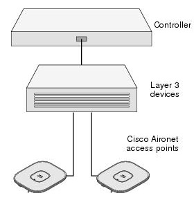
Network Diagram
Pre-Installation Configuration Setup. Below Figure shows the pre-installation configuration setup.
Follow these steps to perform the pre-installation configuration.
Step 1 ![]() Make sure that the Cisco wireless LAN controller DS port is connected to the network. Use the CLI, web-browser interface, or Cisco WCS procedures as described in the appropriate Cisco wireless LAN controller guide.
Make sure that the Cisco wireless LAN controller DS port is connected to the network. Use the CLI, web-browser interface, or Cisco WCS procedures as described in the appropriate Cisco wireless LAN controller guide.
a. ![]() Make sure that access points have Layer 3 connectivity to the Cisco wireless LAN controller Management and AP-Manager Interface.
Make sure that access points have Layer 3 connectivity to the Cisco wireless LAN controller Management and AP-Manager Interface.
b. ![]() Configure the switch to which your access point is to attach. See the Cisco Unified Wireless Network WLAN Controller Guide: Cisco 440x Series WLAN Controllers for additional information.
Configure the switch to which your access point is to attach. See the Cisco Unified Wireless Network WLAN Controller Guide: Cisco 440x Series WLAN Controllers for additional information.
c. ![]() Set the Cisco wireless LAN controller as the master so that new access points always join with it.
Set the Cisco wireless LAN controller as the master so that new access points always join with it.
d. ![]() Make sure DHCP is enabled on the network. The access point must receive its IP address through DHCP.
Make sure DHCP is enabled on the network. The access point must receive its IP address through DHCP.
e. ![]() CAPWAP UDP ports must not be blocked in the network.
CAPWAP UDP ports must not be blocked in the network.
f. ![]() The access point must be able to find the IP address of the controller. This can be accomplished using DHCP, DNS, or IP subnet broadcast.
The access point must be able to find the IP address of the controller. This can be accomplished using DHCP, DNS, or IP subnet broadcast.
This guide describes the DHCP method to convey the controller IP address. For other methods, refer to the product documentation. See also the "Using DHCP Option 43" section for more information.
Step 2 ![]() Apply power to the access point:-
Apply power to the access point:-
a. ![]() The access point is 802.3af (15.4 W) compliant and can be powered by any of the following 802.3af compliant devices:
The access point is 802.3af (15.4 W) compliant and can be powered by any of the following 802.3af compliant devices:
–![]() 2106 controller
2106 controller
–![]() WS-C3550, WS-C3560, and WS-C3750 switches
WS-C3550, WS-C3560, and WS-C3750 switches
–![]() C1880 switch
C1880 switch
–![]() 2600, 2610, 2611, 2621, 2650, and 2651 multiservice platforms
2600, 2610, 2611, 2621, 2650, and 2651 multiservice platforms
–![]() 2610XM, 2611XM, 2621XM, 2650XM, 2651XM, and 2691 multiservice platforms
2610XM, 2611XM, 2621XM, 2650XM, 2651XM, and 2691 multiservice platforms
–![]() 2811, 2821, and 2851 integrated services routers
2811, 2821, and 2851 integrated services routers
–![]() 3620, 3631-telco, 3640, and 3660 multiservice platforms
3620, 3631-telco, 3640, and 3660 multiservice platforms
–![]() 3725 and 3745 multiservice access routers
3725 and 3745 multiservice access routers
–![]() 3825 and 3845 integrated services routers
3825 and 3845 integrated services routers
The recommended external power supply for the access point is the Cisco AIR-PWR-B power supply. The access point can also be powered by the following optional external power sources:
–![]() 1250 series access point power injector (AIR-PWRINJ4)
1250 series access point power injector (AIR-PWRINJ4)
–![]() Any 802.3af compliant power injector
Any 802.3af compliant power injector
Note The 3500 series access point requires a Gigibit Ethernet link to prevent the Ethernet port from becoming a bottleneck for traffic because wireless traffic speeds exceed transmit speeds of a 10/100 Ethernet port.
b. As the access point attempts to connect to the controller, the LEDs cycle through a green, red, and amber sequence, which can take up to 5 minutes.
Note If the access point remains in this mode for more than five minutes, the access point is unable to find the Master Cisco wireless LAN controller.
Check the connection between the access point and the Cisco wireless LAN controller and be sure that they are on the same subnet.
c. If the access point shuts down, check the power source.
d. After the access point finds the Cisco wireless LAN controller, it attempts to download the new operating system code if the access point code version differs from the Cisco wireless LAN controller code version. While this is happening, the Status LED blinks dark blue.
e. If the operating system download is successful, the access point reboots.
Step 3 Configure the access point if required. Use the controller CLI, controller GUI, or Cisco WCS to customize the access-point-specific 802.11n network settings.
Step 4 If the pre-installation configuration is successful, the Status LED is green indicating normal operation. Disconnect the access point and mount it at the location at which you intend to deploy it on the wireless network.
Step 5 If your access point does not indicate normal operation, turn it off and repeat the pre-installation configuration.
Note When you are installing a Layer 3 access point on a different subnet than the Cisco wireless LAN controller, be sure that a DHCP server is reachable from the subnet on which you will be installing the access point, and that the subnet has a route back to the Cisco wireless LAN controller. Also be sure that the route back to the Cisco wireless LAN controller has destination UDP ports 5246 and 5247 open for CAPWAP communications. Ensure that the route back to the primary, secondary, and tertiary wireless LAN controller allows IP packet fragments. Finally, be sure that if address translation is used, that the access point and the Cisco wireless LAN controller have a static 1-to-1 NAT to an outside address. (Port Address Translation is not supported.)
Find answers to your questions by entering keywords or phrases in the Search bar above. New here? Use these resources to familiarize yourself with the community: