- Cisco Community
- Technology and Support
- Service Providers
- Service Providers Knowledge Base
- ASR9000/XR: How to use Port Spanning or Port Mirroring
- Subscribe to RSS Feed
- Mark as New
- Mark as Read
- Bookmark
- Subscribe
- Printer Friendly Page
- Report Inappropriate Content
- Subscribe to RSS Feed
- Mark as New
- Mark as Read
- Bookmark
- Subscribe
- Printer Friendly Page
- Report Inappropriate Content
on
03-20-2011
10:04 AM
- edited on
12-22-2017
09:20 AM
by
Gagandeep Kaur
![]()
Introduction
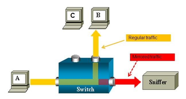
This document provides some extra documentation and use cases on the use of port spanning or port mirroring.
You can monitor traffic passing in & out of a set of L2 or L3 Ethernet interfaces (including bundle-Ether).
Core Issue
ASR 9000 is the only platform implementing SPAN on XR (Only support on ethernet linecards, not on SIP-700.)
You can use SPAN/Mirror in the follow scenarios
- L2 & L3 interfaces.
- Local, R-SPAN, and PW-SPAN only (no ER SPAN.)
- Scale limits:
8 monitor sessions
800 total source ports
1.5 Gig bidirectional replication limit toward fabric for bundle interfaces and 10 Gig ports.
Guideline: ~ 10% - 15% total bandwidth can be mirrored system-wide
- Source ports: Physical, EFPs, and bundles interfaces (L2 & L3)
- Destination ports: Ethernet interfaces, EFPs, and PW-SPAN. (No bundle) [ only L2 transport interfaces are supported as destination ports]
- Ability to use ACL's to define which traffic is to be captured
- Capture multicast traffic is possible
Note: some of the functionality mentioned are enhancements to the XR 4.0.1 release, this document assumes you are using this release or later.
A good reference on the terminology of SPAN/Mirror can be found here:
http://www.cisco.com/en/US/docs/switches/lan/catalyst6500/ios/12.2SX/configuration/guide/span.pdf
SPAN order of operation
SPAN mirrors what is on the wire
For ingress, this means packets are mirrored before QOS, ACL, and encapsulation rewrite operations.
For egress, this means packets are mirrored after QOS, ACL, and encapsulation rewrite operations.
Partial Packet Mirroring
User can configure to mirror first 64 upto 256 bytes of the packet.
Note: The actual mirrored packet will be the configured size plus 4-byte trailling CRC.
Sample config:
interface GigabitEthernet0/6/0/20 l2transport
monitor-session PW
mirror first 100 <== valid range: [64, 256], inclusively
!
!
Note: The mirrored packet received at sniffer will have the size of 104
(4-byte of trailing CRC added by transmit MAC layer.)
ACL based Mirroring
“permit/deny” determines the behavior of the regular traffic (forwarded or dropped)
“capture” determines whether the packet is mirrored to the SPAN destination.
On SPAN: mirror traffic on the wire (regardless with or without ACL.)
ACL on ingress direction:
SPAN will mirror traffic even regular traffic dropped by ACL: Always mirror!
ACL on egress direction
Will mirror if regular traffic is forwarded (Permit)
Will not mirror if regular traffic is dropped (Deny.)
Inconsistent configurations:
“acl” is configured on SPAN source port but
ACL has no “capture” keyword:
No traffic gets mirrored.
“acl” is NOT configured on SPAN source port but
ACL has “capture” keyword:
Mirroring traffic as normal, no ACL performed.
The ACL can also be an L2 ACL :
ethernet-services access-list esacl_t2
10 deny 1234.5678.90ab 0000.0000.0000 any capture
L3 Spanning Example
monitor-session TEST
destination interface GigabitEthernet0/1/0/2 (<<<< this is NP3)
!
interface GigabitEthernet0/1/0/14 (<<<< this is NP2)
ipv4 address 5.5.1.1 255.255.255.0
monitor-session TEST
acl
!
load-interval 30
ipv4 access-group span ingress
!
ipv4 access-list span
10 permit ipv4 any host 1.1.1.10 capture
15 permit ipv4 any host 239.1.1.1 capture
20 permit ipv4 any host 2.2.2.100
30 permit ipv4 any any
Sample TRAFFIC GEN: (sending multicast in this example)
tgn rate 1000
L2-dest-addr 0100.5E01.0101
L2-src-addr 0003.A0FD.28A8
L3-src-addr 5.5.1.2
L3-dest-addr 239.1.1.1
Checking NP2: (the port that we are spanning)
Show global stats counters for NP2, revision v3
Read 12 non-zero NP counters:
Offset Counter FrameValue Rate (pps)
-------------------------------------------------------------------------------
22 PARSE_ENET_RECEIVE_CNT 5478 1001
31 PARSE_INGRESS_DROP_CNT 3 1
33 RESOLVE_INGRESS_DROP_CNT 5474 1000
(there is no mcast recipient for this mcast addr, but we’re still replicating, see red line)
40 PARSE_INGRESS_PUNT_CNT 1 0
50 MODIFY_RX_SPAN_CNT 5475 1000
54 MODIFY_FRAMES_PADDED_CNT 5475 1000
68 RESOLVE_INGRESS_L3_PUNT_CNT 1 0
104 LOOP 1 0
224 PUNT_STATISTICS 9 2
480 RESOLVE_IPM4_ING_RTE_DROP_CNT 5475 1000
565 UIDB_TCAM_MISS_AGG_DROP 3 1
570 UIDB_TCAM_MISS_PORT4_DROP_FOR_HOST 3 0
NP3 is the span monitor interface:
Show global stats counters for NP3, revision v3
Read 16 non-zero NP counters:
Offset Counter FrameValue Rate (pps)
-------------------------------------------------------------------------------
22 PARSE_ENET_RECEIVE_CNT 36 0
23 PARSE_FABRIC_RECEIVE_CNT 79656 1000
30 MODIFY_ENET_TRANSMIT_CNT 79655 1000
Packets received from fabric and sent off to the Ethernet on the span port!
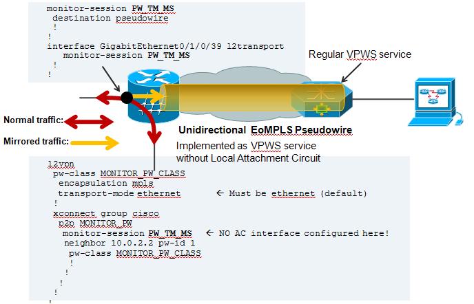
PW SPAN example
For PW span to work, you need to define a local monitor session with a destination pseudo wire. You apply that span session to the interface of interest and define an xconnect group that also leverages that span session as one of the pw ends.
On the remote side where the PW terminates, you just configure regular VPWS.
Here an example:
On the Local Side, besides my Span configuration, there is also a local cross connect between the interested session we want to span over the PW
l2vpn
xconnect group TEST
p2p TEST
interface GigabitEthernet0/1/0/39
! port 39 is the port where we apply the span on.
interface GigabitEthernet0/1/0/20.100
! this is just a random AC to have traffic flowing between the spanned port.
!
AC configuration:
interface GigabitEthernet0/1/0/20.100 l2transport
encapsulation dot1q 100
rewrite ingress tag pop 1 symmetric
! the tag is popped because the other XCON end is a plain ethernet without vlan. The explanation and use cases of tag popping can be found a related
! Tech note article.
Configuration on the remote side:
Regular VPWS configuration:
RP/0/RSP0/CPU0:A9K-TOP#sh run l2vpn
l2vpn
xconnect group PW-SPAN
p2p PW-SPAN_1
interface GigabitEthernet0/0/0/39
neighbor 2.2.2.2 pw-id 1
!
!
!
interface GigabitEthernet0/0/0/39
load-interval 30
transceiver permit pid all
l2transport
!
!
the neighbor in the l2vpn configuration is the LDP neighbor ID
between which the PW is built.
Show on remote side:
RP/0/RSP0/CPU0:A9K-TOP#show l2vpn xcon group PW-SPAN det
Group PW-SPAN, XC PW-SPAN_1, state is up; Interworking none
AC: GigabitEthernet0/0/0/39, state is up
Type Ethernet
MTU 1500; XC ID 0x4000a; interworking none
Statistics:
packets: received 0, sent 16570475
bytes: received 0, sent 994228500
! packets received from the PW are sent out hte Attachment circuit's interface. The analyzer is connected to G0/0/0/39
PW: neighbor 2.2.2.2, PW ID 1000, state is up ( established )
PW class not set, XC ID 0x4000a
Encapsulation MPLS, protocol LDP
PW type Ethernet, control word disabled, interworking none
PW backup disable delay 0 sec
Sequencing not set
MPLS Local Remote
------------ ------------------------------ -----------------------------
Label 16002 16027
Group ID 0xa40 0x2
Interface GigabitEthernet0/0/0/39 PW/TM/MS
MTU 1500 1500
Control word disabled disabled
PW type Ethernet Ethernet
VCCV CV type 0x2 0x2
(LSP ping verification) (LSP ping verification)
VCCV CC type 0x6 0x6
(router alert label) (router alert label)
(TTL expiry) (TTL expiry)
------------ ------------------------------ -----------------------------
MIB cpwVcIndex: 4294705162
Create time: 04/04/2011 14:36:42 (00:20:07 ago)
Last time status changed: 04/04/2011 14:36:42 (00:20:07 ago)
Statistics:
packets: received 16570475, sent 0
bytes: received 994228500, sent 0
! Packets received on the Pseudo Wire from the SPAN port
NOTE: Pseudo Wire counters on the span side are not incrementing.That is the XCON group "cisco" in this picture config example.
This is intentional. You can review the SPANNING also with this command:
RP/0/RSP1/CPU0:A9K-BOTTOM#sh monitor-session counters
Monitor-session PW_TM_MS
GigabitEthernet0/1/0/39
Rx replicated: 58488205 packets, 3743245120 octets
Tx replicated: 58488206 packets, 3743245184 octets
Non-replicated: 0 packets, 0 octets
R-SPAN configuration:
R-SPAN is natively support with the capability of ASR9000 to do vlan imposition:
monitor-session MS2
destination interface gig0/2/0/19.10
!
interface gig0/2/0/12.10 l2transport
encapsulation dot1q 10 <<< Monitoring vlan 10 traffic
monitor-session MS2
!
interface gig0/2/0/19.10 l2transport (*)
encapsulation dot1q 100 <<< VLAN 100 will get imposed.
!
(*) Monitor destination could be any supported destination interface regardless of monitor source
Related Information
n/a
Xander Thuijs, CCIE #6775
Sr. Tech Lead ASR9000
- Mark as Read
- Mark as New
- Bookmark
- Permalink
- Report Inappropriate Content
We went from IOS-XR 5.1.3 to 5.3.3 today on our ASR9010 and SPAN ports killed our thruput.
Config:
monitor-session No1 ethernet
destination interface TenGigE0/1/1/4
!
monitor-session No2 ethernet
destination interface TenGigE0/1/1/5
!
interface GigabitEthernet0/1/0/10
monitor-session No1 ethernet
!
interface TenGigE0/0/1/2
monitor-session No2 ethernet
!
interface TenGigE0/1/1/7
monitor-session No1 ethernet
!
interface TenGigE0/1/1/7.100
monitor-session No1 ethernet
!
interface TenGigE0/1/1/7.333
monitor-session No1 ethernet
!
interface TenGigE0/1/1/7.667
monitor-session No1 ethernet
We didn't see any CPU spikes, no pkt loss on interfaces - just output drops on destination SPAN port (doesn't bother us), but what killed us was pkt loss on the interfaces being SPANed (source, not destination). This caused us major headaches.
This worked perfectly well with 5.1.3. Is there some known bug in 5.3.3 about this?
Thanks!
- Mark as Read
- Mark as New
- Bookmark
- Permalink
- Report Inappropriate Content
Xander,
We urgently need that ability to split rx and tx traffic as Hendro requested two years ago. Any change since then?
Reason: we had been on 5.1.3 and upgraded to 5.3.3 about a month ago and encountered an unknown bug which causes silent pkt loss on the source port when the destination port is over-subscribed. For example, if we have 6Gb/sec tx and 5Gb/sec rx on a 10Gb/sec port and we SPAN rx+tx to a 10Gb/sec port, previously under 5.1.3, the excess pkts on the destination port would be thrown away - that we can live with. But now with 5.3.3 we are having pkt loss on the source port which is something we can't live with.
This has been open with Cisco TAC now for a month via SR 681268561. But we need a bypass and were thinking of splitting rx+tx in the meantime. It would appear that is not supported.
Any other ideas?
Thanks!
- Mark as Read
- Mark as New
- Bookmark
- Permalink
- Report Inappropriate Content
hi hank,
the functionality to set up 2 monitor sessions one for RX and one for TX is not possible still.
I did come aware of a similar issue whereby span on a subinterface causes packet drop on the spanned/monitored interface. there seems a similarity there.
one thing that I saw standing out in the config is that you are using netflow 1:1 and span, at high traffic rates this will overload the npu quite a bit. netflow will replicate every packet, and so does span, each copy requiring a different processing for its service. so you'll get 3 copies through the pipeline already.
One possible temporary solution could be to use bridge domain and flooding.
create a BD, put two destinations in there, and disable mac learning, than we can leverage the fabric replication instead of using npu replication in the bound direction and only a single copy replication in the egress direction.
Looking at the case some other separate actions are needed also, and I will follow up with that separately also so you get better service you should receive!
xander
- Mark as Read
- Mark as New
- Bookmark
- Permalink
- Report Inappropriate Content
Seasons greetings to all. We wish to SPAN to a 40Gig port on our ASR9000.
Cisco compatibility matrix shows the following QSFPs work:
http://www.cisco.com/c/en/us/td/docs/interfaces_modules/transceiver_modules/compatibility/matrix/40GE_Tx_Matrix.html?referring_site=RE&pos=1&page=http://www.cisco.com/c/en/us/products/collateral/interfaces-modules/transceiver-modules/data_sheet_c78-660083.html#_Toc466988081
But since we have available multiple 10Gig ports we were hoping to use:
QSFP-4X10G-AC10M=
http://www.cisco.com/c/en/us/td/docs/interfaces_modules/transceiver_modules/installation/note/OL_24862.html
But this cable doesn't appear in the ASR9000 compability matrix. Does that mean it won't work?
Thanks!
- Mark as Read
- Mark as New
- Bookmark
- Permalink
- Report Inappropriate Content
hi hank, best wishes to you!
when it is not in the compatibility matrix, that means we dont test it in our setups. it also means that by default the unrecognized optic wont be brought up, but you have an override for it via
service unsupported-tranceiver (allow unrecognized vendor) and the interface level tranceiver permit pid all (allow recognized vendor but unrecognized pid). One or both may be needed.
this will try to bring up the optic via "standard" procedures. it may or may not work. enhanced feats like dom especially can be sensitive here, but basic interface bring up may be fine.
when i checked the driver codes, I dont see a specific entry for it, so I dont know how it will work, but can always give it a try. Using an unsupported tranceiver doesnt mean that tac wont support you, it merely means we didnt test for it and dont know what if how :)
regards
xander
- Mark as Read
- Mark as New
- Bookmark
- Permalink
- Report Inappropriate Content
Does Cisco recognize how great you are and how useful this forum is to people trying to implement things on their ASR9000s?
May life only provide you with good and happy thing!
-Hank
- Mark as Read
- Mark as New
- Bookmark
- Permalink
- Report Inappropriate Content
Well, it's important that we do!
But, I also think that Cisco is aware how much Xander and Aleksandar help us when we are stuck.
- Mark as Read
- Mark as New
- Bookmark
- Permalink
- Report Inappropriate Content
you know hank and smail, it is people like you that make it so much fun to do and worthwhile :) thanks so much for the nice comments!! makes my day, really!! :)
more in 2017! for sure! :)
cheers!!
xander and aleks :)
- Mark as Read
- Mark as New
- Bookmark
- Permalink
- Report Inappropriate Content
What is the performance hit for doing 40G SPAN? Does it make a difference if the 40G port is dest or source? The SPA is located on a A9K-MOD160-TR linecard.
Thanks!
- Mark as Read
- Mark as New
- Bookmark
- Permalink
- Report Inappropriate Content
the interface type hank doesnt really matter, for span on typhoon and tomahawk linecards it is merely a pps limitation. so the bw doesnt matter, it is the packetsize with bandwidth that matters since that yields the pps that need to be replicated.
if everything is replicated, basically you get a double copy for every packet. obviously the replicated packet doesnt need the same features as the original, so it may not be a 50% hit per-se, but on racetrack, no features, it is. if you add qos, acl etc those feats arent applied to the spanned packet, hence the perf hit is not 50% on top of what you have now as max pps.
cheers
xander
- Mark as Read
- Mark as New
- Bookmark
- Permalink
- Report Inappropriate Content
Thanks. Is there a table someplace we can figure it out on our own? Does this mean that if I have 2x 40G ports as destination and I am replicating 8x 10G ports to those two SPAN dest ports - the performance hit will be 100%?
- Mark as Read
- Mark as New
- Bookmark
- Permalink
- Report Inappropriate Content
hi hank, yeah that is tricky, as you noticed I tend to explain how things work so you can fill in the variables to identify what the hit would be, since it is so hard to give a single solid number as there are so many dependencies...
so for the ingress npu, it receives traffic from the interface. lets say there are no features and everything is replicated. then the perf hit is perfectly 50% since we have to operate on every packet twice.
for the npu with the destination interfce, for him it is just another packet, so tx operation only, and likely no features.
if you have on the ingress interface features running that cost you say 30% like qos and acl. then the total add on for span is not plus 50. since the span packets dont need acl and qos and just need to get to the destination npu.
if you have 2x40G as destination and 8x10 source and you span everything then ALL bw is consumed on the span destinations.
whether the npu's serving the 8x10 are overloaded depends on the features and the interface to npu mapping/load.
cheers
xander
- Mark as Read
- Mark as New
- Bookmark
- Permalink
- Report Inappropriate Content
> note that from fab (egress) or from line (ingress) are always high priority for the NPU to process.
> pipeline replication (eg span) is lower priority.
> so spanned traffic would never push away in/egress traffic
Hi Xander,
Where are the recirculated packets inserted into the NPU's pipeline please?
Is it via the feeder queues (via ICU and queued at the ICFDQs) as normal WAN traffic -but there are only 3 priority levels currently used (out of 4) so not sure how the above statement holds true.
Or maybe there are dedicated ICFDQs with lowest possible priority for recirculated traffic so that ingress TM can let these queues to be starved out in case of NPU overload?
But m-cast could also be recirculated -so would it be treated with lowest possible priority at the NPU's feeder queue in that case?
Though the question still remains, why it is a problem all of a sudden when upgrading from 5.1.3 to 5.3.3.
Thank you very much
adam
- Mark as Read
- Mark as New
- Bookmark
- Permalink
- Report Inappropriate Content
This was a great help!!! Thanks. The PW SPAN example worked perfectly. Saved me a bunch of travel time. Thanks again! RReichel
- Mark as Read
- Mark as New
- Bookmark
- Permalink
- Report Inappropriate Content
Hi Xander,
How can we capture LACP packets from ASR9010 (6.1.3) in Tx and RX direction. We have tried Traffic Mirroring with Physical Interfaces. But LACP packets were not getting captured on Laptop (wireshark).
http://www.cisco.com/c/en/us/td/docs/routers/asr9000/software/asr9k_r4-1/interfaces/configuration/guide/hc41asr9kbook/hc41span.pdf
Find answers to your questions by entering keywords or phrases in the Search bar above. New here? Use these resources to familiarize yourself with the community: