- Cisco Community
- Technology and Support
- Networking
- Switching
- 3850 Stack Power
- Subscribe to RSS Feed
- Mark Topic as New
- Mark Topic as Read
- Float this Topic for Current User
- Bookmark
- Subscribe
- Mute
- Printer Friendly Page
- Mark as New
- Bookmark
- Subscribe
- Mute
- Subscribe to RSS Feed
- Permalink
- Report Inappropriate Content
06-09-2015 04:58 PM - edited 03-10-2019 12:31 PM
Hello,
I have a stack of 7 3850's that I am preparing for deployment. Can anyone help me out with a diagram of how the Stackpower cables should be configured? Also does the stack need to be powered off when installing those cables or can that be done hot? Thanks in advance for the help.
Solved! Go to Solution.
- Labels:
-
Other Switching
Accepted Solutions
")
- Mark as New
- Bookmark
- Subscribe
- Mute
- Subscribe to RSS Feed
- Permalink
- Report Inappropriate Content
06-09-2015 09:09 PM
Yes it is possible.
Up to four switches can be configured in a StackPower stack using the StackPower cable
HTH
Regards
Inayath
- Mark as New
- Bookmark
- Subscribe
- Mute
- Subscribe to RSS Feed
- Permalink
- Report Inappropriate Content
06-09-2015 05:03 PM
Hi,
Please find below links which will help you:-
http://www.cisco.com/c/en/us/td/docs/switches/lan/catalyst3850/software/release/3se/ha_stack_manager/configuration_guide/b_hastck_3se_3850_cg/b_hastck_3se_3850_cg_chapter_010.html
Regards
Inayath
- Mark as New
- Bookmark
- Subscribe
- Mute
- Subscribe to RSS Feed
- Permalink
- Report Inappropriate Content
06-09-2015 05:07 PM
Basicly, you need to have the same exact IOS in all your switches with the same license level. For example, if you purchased IP base license level, it should be the same for all switches. The other thing that you want to do is to assign priorities to your switches, so you always know which switch is the master and if the master fails what switch becomes the master.
I usually assign the highest priority (15) to the master and the first member get 12 and the next member 10 and so on. This way, I know, if switch-1 (the master) fails, switch 2 with priority 12 will be the next master and so on....
here is good doc for reference to start with.
BTW, you don't need any config on the member switches, you only configure the master.
http://www.cisco.com/en/US/docs/switches/lan/catalyst3850/hardware/installation/guide/HIGINSTL.html
- See more at: https://supportforums.cisco.com/discussion/11868511/3850-switch-stack-configuration-assistance#sthash.N8NtNdCR.dpuf
HTH
Regards
Inayath
*Please do not forget to rate all usefull posts.
- Mark as New
- Bookmark
- Subscribe
- Mute
- Subscribe to RSS Feed
- Permalink
- Report Inappropriate Content
06-09-2015 05:12 PM
Switch Stacking and Power Stacking Guidelines
Before connecting the switches in a stack, keep in mind these stacking guidelines:
Size of the switch and any optional power-supply module. The 1100-W power-supply module is longer than the other modules. Stacking switches with the same power-supply modules together makes it easier to cable the switches.
- Length of cable. Depending on the configurations that you have, you might need different-sized cables. If you do not specify the length of the StackWise cable, the 0.5-meter cable is supplied. If you need the 1-meter cable or the 3-meter cable, you can order it from your Cisco supplier. For cable part numbers, see StackWise Ports. The Data Stack Cabling Configurations provides examples of recommended configurations.
- For rack-mounted switch stacks that are members of a StackPower stack as well as a data stack, see Planning a StackPower Stack.
- You can create data stacks with up to nine switches in a stack.
Data Stack Cabling Configurations
This is an example of a recommended configuration that uses the supplied 0.5-meter StackWise cable. In this example, the switches are stacked in a vertical rack or on a table. This configuration provides redundant connections. The configuration example uses the supplied 0.5-meter StackWise cable. The example shows the full-ring configuration that provides redundant connections.

This example shows a recommended configuration when the switches are mounted side-by-side. Use the 1-meter and the 3-meter StackWise cables to connect the switches. This configuration provides redundant connections.
Data Stack Bandwidth and Partitioning Examples
This section provides examples of data stack bandwidth and possible data stack partitioning. The figure shows a data stack of Catalyst 3850 switches that provides full bandwidth and redundant StackWise cable connections.

This figure shows an example of a stack of Catalyst 3850 switches with incomplete StackWise cabling connections. This stack provides only half bandwidth and does not have redundant connections.

The figures below show data stacks of Catalyst 3850 switches with failover conditions. In this figure, the StackWise cable is bad in link 2. Therefore, this stack provides only half bandwidth and does not have redundant connections.

In this figure, link 2 is bad. Therefore, this stack partitions into two stacks, and the top and bottom switches become the active switch in the stack. If the bottom switch is a member (not active or standby switch), it reloads.

Power-On Sequence for Switch Stacks
Consider these guidelines before you power on the switches in a stack:
The sequence in which the switches are first powered on might affect the switch that becomes the stack master.
- There are two ways to elect an active switch:
- If you want a particular switch to become the active switch, configure it with the highest priority. Among switches with same priority, the switch with the lowest MAC address becomes the active switch.
If you want a particular switch to become the active switch, power on that switch first. This switch remains the active switch until a reelection is required. After 2 minutes, power on the other switches in the stack. If you have no preference as to which switch becomes the active switch, power on all the switches in the stack within 1 minute. These switches participate in the active switch election. Switches powered on after 2 minutes do not participate in the election.
If changes are made to the stack without powering down the switches, the following results can occur:
If two operating partial ring stacks are connected together using a stack cable, a stack merge can take place. This situation reloads the whole stack (all switches in the stack).
- If some switches in the stack are completely separated from the stack, a stack split can occur.
- A stack split can occur on a full ring stack if:
- In a split stack, depending on where the active and standby switches are located, either two stacks might be formed (with the standby taking over as the new active switch in the newly formed stack) or all the members in the newly formed stack might reload.
 Note | These results depend on how the switches are connected. You can remove two or more switches from the stack without splitting the stack. |
For conditions that can cause a stack reelection or to manually elect the active switch, see the stacking software configuration guide on Cisco.com at this URL: http://www.cisco.com/go/cat3850_docs.
Planning a StackPower Stack
StackPower Stacking Guidelines
You can configure a StackPower stack for either power sharing or redundancy. In power-sharing mode, the power of all the power supplies in the stack is aggregated and distributed among the stack members.
In redundant mode, when the total power budget of the stack is calculated, the wattage of the largest power supply is not included. That power is held in reserve and used to maintain power to switches and attached devices when one power supply fails. Following the failure of a power supply, the StackPower mode becomes power sharing.
Note | Power-sharing mode is the recommended configuration for Catalyst 3850 switches. |
For general concepts and management procedures for switch power stacks, see the software stacking configuration guide on Cisco.com.
- A switch power stack can include a maximum of four switches in a ring topology and nine switches in a star topology.
- Size of the switch and any optional power supply module. The 1100-W power-supply module is 1.5 inches (3.81 cm) longer than the other modules, and with the attached cable retention clip, it extends 3 inches (7.62 cm) from the switch chassis. Stacking switches with the same power-supply modules together makes it easier to cable the switches. For switch dimensions, see Appendix A, “Technical Specifications.”
- Length of cable. Depending on the configurations that you have, you might need different-sized cables. If you do not specify the length of the StackPower cable, the 0.3 meter cable is supplied. If you need the 1.5 meter cable, you can order it from your Cisco supplier. For cable part numbers, see StackPower Connector. The StackPower Cabling Configurations provides examples of recommended configurations.
- For rack-mounted switch stacks that are members of a data stack and a StackPower stack, see Switch Stacking and Power Stacking Guidelines.
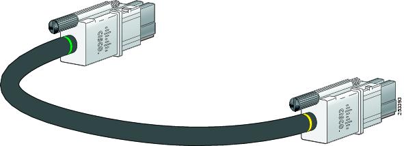
StackPower Cabling Configurations
This section describes the recommended cabling configurations for a StackPower stack. There are two types of StackPower cables.
The cable is available in two lengths.
| Part Number | Cable Type | Length |
|---|---|---|
| CAB-SPWR-30CM | StackPower Cable | 0.3 meter |
| CAB-SPWR-150CM | StackPower Cable | 1.5 meter |
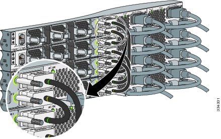
This figure shows a ring configuration using both of the supplied 0.3-meter StackPower cables and one 1.5-meter cable. In the examples that follow, the switches are stacked in a vertical rack or on a table.
This figure shows nine switches connected in a star topology.

StackPower Partitioning Examples
These figures show StackPower stacks of Catalyst 3850 switches with failover conditions.
In this figure, the StackPower cable 2 is faulty. Therefore, this stack does not provide redundancy.

In this figure, StackPower port B on the center switch has failed and this stack partitions into two stacks. The top two switches share power, and the bottom switch is now a separate stack.

HTH
Regards
Inayath
*Please do not forget to rate all usefull posts.
- Mark as New
- Bookmark
- Subscribe
- Mute
- Subscribe to RSS Feed
- Permalink
- Report Inappropriate Content
06-09-2015 05:57 PM
Thanks for the info, I have read most if not all of the documentation. My question is only regarding the stackpower aspect of it. I already have the stackwise configuration set up fine. From what i can gather if i want to have full redundancy with 7 switches i have to also purchase an XPS along with longer cables i suspect. Is it possible to configure the set up I have now with a 4 and 3 setup in regards to stackpower only. I need to keep the 7 switch stack 1 logical unit in terms of stackwise. Basically what are my options with the equipment that i have now. thanks
- Mark as New
- Bookmark
- Subscribe
- Mute
- Subscribe to RSS Feed
- Permalink
- Report Inappropriate Content
06-09-2015 09:09 PM
Yes it is possible.
Up to four switches can be configured in a StackPower stack using the StackPower cable
HTH
Regards
Inayath
- Mark as New
- Bookmark
- Subscribe
- Mute
- Subscribe to RSS Feed
- Permalink
- Report Inappropriate Content
06-10-2015 07:15 AM
Thanks for the help. I was able to get it working correctly now. I basically made 1 power stack with 4 switches and another with 3 switches. The Cisco documentation is severely lacking regarding Stack-Power. You pretty much have to search the internet to find the obscure commands to get anything other than the default working.
http://www.ccierants.com/2011/08/configuring-stack-power-what-they-dont.html
http://www.postseek.com/meta/34adeef29d2232faab3eebcb2534a877
- Mark as New
- Bookmark
- Subscribe
- Mute
- Subscribe to RSS Feed
- Permalink
- Report Inappropriate Content
12-08-2015 07:12 AM
For all of you that are still interested in this scenario - I found that this Cisco doc can be pretty useful (3850 Deployment Guide - Stacking section):
Thanks for the previous posts.
- Mark as New
- Bookmark
- Subscribe
- Mute
- Subscribe to RSS Feed
- Permalink
- Report Inappropriate Content
12-17-2015 09:27 AM
Hi,
Just to clarify. Can the stack power cables be inserted/remove hot while the switches are already powered.
I have an issue with the stack power with errors appearing stack power inserted/removed regularly. I suspect that one of the cables is not properly connected, so i want to disconnect and connect it without powering off the switch stack.
Can this be done hot?
Thanks.
- Mark as New
- Bookmark
- Subscribe
- Mute
- Subscribe to RSS Feed
- Permalink
- Report Inappropriate Content
12-23-2015 12:40 AM
Did it hot? Removed and Inserted the cables while switch is powered and it works no issue.
Discover and save your favorite ideas. Come back to expert answers, step-by-step guides, recent topics, and more.
New here? Get started with these tips. How to use Community New member guide