- Cisco Community
- Technology and Support
- Networking
- Switching
- Re: Deploying the L2 /L3 Boundary at the Distribution Layer
- Subscribe to RSS Feed
- Mark Topic as New
- Mark Topic as Read
- Float this Topic for Current User
- Bookmark
- Subscribe
- Mute
- Printer Friendly Page
- Mark as New
- Bookmark
- Subscribe
- Mute
- Subscribe to RSS Feed
- Permalink
- Report Inappropriate Content
08-18-2011 12:07 PM - edited 03-07-2019 01:46 AM
Could someone explain the various link-failover mechanisms and how they work in this particular design?
Cisco describes this approach, "The time-proven topology that provides the highest availability does not require STP/RSTP convergence. In this topology, no VLANs span access layer switches and the distribution layer interconnection is an L3 point-to-point link. From an STP perspective, both access layer uplinks are forwarding, so the only convergence dependencies are the default gateway and return path route selection across the distribution-to-distribution link.
How does this stack up against the traditional L2 Etherchannel between the Core/Distribution 6509s design?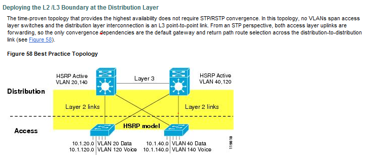
Solved! Go to Solution.
- Labels:
-
Other Switching
Accepted Solutions
- Mark as New
- Bookmark
- Subscribe
- Mute
- Subscribe to RSS Feed
- Permalink
- Report Inappropriate Content
08-18-2011 01:55 PM
No need to apologize, these forums are here to answer questions
Vlan 10 at layer 2 ie. in the vlan database needs to exist on all 3 switches - as1/ds1/ds2.
Vlan 10 L3 interfaces would be on ds1 and ds2 only. You configure an ip address from the same subnet on each vlan 10 interface and then a common IP which is the HSRP virtual IP eg.
ds1
===
int vlan 10
ip address 192.168.5.2 255.255.255.0
standby 10 ip 192.168.5.1 <--- this is the virtual IP
standby 10 priority 110
standby 10 preempt
standby 10 authenticaion
ds2
===
int vlan 10
ip address 192.168.5.3 255.255.255.0
standby 10 ip 192.168.5.1
standby 10 authentication
in the above ds1 would be the HSRP active gateway because it has a HSRP priority of 110 (100 is the default which is what ds2 is using). You use the virtual IP of 192.168.5.1 as the default-gateway on your clients in vlan 10 and they would use addresses from the 192.168.5.0/24 subnet.
The L3 interconnect is not in vlan 10. You would generally make it a routed link ie. it wouldn't be in any vlans because it doesn't need to be. All the L3 link is for is so the distribution switches can exchange routes and advertise routes to any other L3 devices. Optionally instead of a routed link it could be a dedicated vlan ie. one not used for anything else just for ds1 and ds2 to peer with each other but if you can i would generally use routed links.
If you did use a dedicated vlan for peering then you would need SVIs for that vlan on each switch ie. ds1 and ds2 but there is no need for HSRP configuration as there are no end devices in this vlan.
Jon
- Mark as New
- Bookmark
- Subscribe
- Mute
- Subscribe to RSS Feed
- Permalink
- Report Inappropriate Content
08-18-2011 02:18 PM
If the uplink from as1 to ds1 fails then yes both ds1 and ds2 become active for vlan 10. However from the perspective of as1 this is not an issue because as1 only has the uplink to ds2 left so it just forwards all client traffic to that switch.
This is also partly why in this design you limit vlans to specific access-layer switches. If you look at the diagram you posted you'll see that each access-layer switch has different vlans on it. No vlan occurs on more than one access-layer switch. And it means that you only have HSRP hellos going between ds1 and ds2 for each vlan via the specific access-layer switch responsible for that vlan.
Jon
- Mark as New
- Bookmark
- Subscribe
- Mute
- Subscribe to RSS Feed
- Permalink
- Report Inappropriate Content
08-18-2011 12:19 PM
The key thing with this design using the L3 interconnect is as you say, both uplinks are forwarding. So if one of the uplinks fails traffic is immediately sent over the other link. Not only does this provide fast failover it also allows you to use the full bandwdith from of the uplinks for each vlan.
With the L2 etherchannel interconnect between the distro switches the normal setup is that one of the uplinks from the access-layer switch is blocked or blocked per vlan more specifically. If the link fails then you are relying on STP to unblock the other link for those vlans.
Now with RSTP or STP with uplinkfast the failover is comparable but you still don't get the full bandwidth from the access-layer.
Another additional point is GLBP. With the traditional L2 etherchannel interconnect GLBP is not optimal. That is because both distro switches can be forwarders for clients in the same vlan. But you only have one uplink from the access-layer switches for each vlan active at one time. So if the uplink from as1 (access switch 1) to ds1 (distro switch 1) is active but ds2 (distro switch 2) is the forwarder for the client traffic must go -
as1 -> ds1 -> ds2
whereas with a L3 interconnect because both uplinks are forwarding you can go directly from as1 -> ds2.
Jon
- Mark as New
- Bookmark
- Subscribe
- Mute
- Subscribe to RSS Feed
- Permalink
- Report Inappropriate Content
08-18-2011 01:14 PM
OK, I see what you're saying, but can you go into more detail about how as1 forwards over both links at the same time with HSRP in the mix? The Cisco ARCH guide says that this works with HSRP or w/ GLBP.
How do the HSRP hellos get sent? ds1 -> as1 -> ds2 ? They obviously can't travel over the L3 interconnect. Can yo describe the failover scenario?
- Mark as New
- Bookmark
- Subscribe
- Mute
- Subscribe to RSS Feed
- Permalink
- Report Inappropriate Content
08-18-2011 01:33 PM
Okay 2 separate things here.
1) forwarding from as1 with HSRP on the distro switches. Basically it doesn't forward over both links for the same vlan from as1. It would only forward over the link that connected to the HSRP active switch. The other link would be unused. But note that is unused for that vlan so you would definitely want to spread your HSRP active gateways across ds1 and ds2.
Also it's important to note that return traffic to the client could come via either link depending on which distro switch the return traffic arrives at.
So client to HSRP active gateway always on the same link. Return traffic could use either link.
2) HSRP hellos. These are sent via the access switch as1 in our case because they cannot be sent across the L3 interconnect link. So imagine the following -
as1 is connected to ds1 and ds2.
as1 has vlan 10 on it.
ds1 is the HSRP active for vlan 10
HSRP hellos for vlan 10 are sent via as1.
If the link from as1 to ds1 fails or ds1 fails etc. then the HSRP hello no longer have a path between ds1 and ds2 for vlan 10. So ds2 now becomes the active gateway for HSRP and as1 simply sends all traffic for the HSRP virtual IP to ds2 instead.
Jon
- Mark as New
- Bookmark
- Subscribe
- Mute
- Subscribe to RSS Feed
- Permalink
- Report Inappropriate Content
08-18-2011 01:46 PM
OK, I'm almost there, but I'm a little confused about VLAN 10. It exists on both ds1 and ds2 (and as1), correct? What about SVIs for HSRP? Do I use SVIs for the real interfaces on the VLAN and a standby IP? What IPs do I use for the L3 interconnect? Are they also in VLAN10?
I apologize for the barrage of questions...
- Mark as New
- Bookmark
- Subscribe
- Mute
- Subscribe to RSS Feed
- Permalink
- Report Inappropriate Content
08-18-2011 01:55 PM
No need to apologize, these forums are here to answer questions
Vlan 10 at layer 2 ie. in the vlan database needs to exist on all 3 switches - as1/ds1/ds2.
Vlan 10 L3 interfaces would be on ds1 and ds2 only. You configure an ip address from the same subnet on each vlan 10 interface and then a common IP which is the HSRP virtual IP eg.
ds1
===
int vlan 10
ip address 192.168.5.2 255.255.255.0
standby 10 ip 192.168.5.1 <--- this is the virtual IP
standby 10 priority 110
standby 10 preempt
standby 10 authenticaion
ds2
===
int vlan 10
ip address 192.168.5.3 255.255.255.0
standby 10 ip 192.168.5.1
standby 10 authentication
in the above ds1 would be the HSRP active gateway because it has a HSRP priority of 110 (100 is the default which is what ds2 is using). You use the virtual IP of 192.168.5.1 as the default-gateway on your clients in vlan 10 and they would use addresses from the 192.168.5.0/24 subnet.
The L3 interconnect is not in vlan 10. You would generally make it a routed link ie. it wouldn't be in any vlans because it doesn't need to be. All the L3 link is for is so the distribution switches can exchange routes and advertise routes to any other L3 devices. Optionally instead of a routed link it could be a dedicated vlan ie. one not used for anything else just for ds1 and ds2 to peer with each other but if you can i would generally use routed links.
If you did use a dedicated vlan for peering then you would need SVIs for that vlan on each switch ie. ds1 and ds2 but there is no need for HSRP configuration as there are no end devices in this vlan.
Jon
- Mark as New
- Bookmark
- Subscribe
- Mute
- Subscribe to RSS Feed
- Permalink
- Report Inappropriate Content
08-18-2011 02:05 PM
Are there any split-brained HSRP issues when an access switch uplink fails? Do both distribution switches think they're HSRP active?
- Mark as New
- Bookmark
- Subscribe
- Mute
- Subscribe to RSS Feed
- Permalink
- Report Inappropriate Content
08-18-2011 02:18 PM
If the uplink from as1 to ds1 fails then yes both ds1 and ds2 become active for vlan 10. However from the perspective of as1 this is not an issue because as1 only has the uplink to ds2 left so it just forwards all client traffic to that switch.
This is also partly why in this design you limit vlans to specific access-layer switches. If you look at the diagram you posted you'll see that each access-layer switch has different vlans on it. No vlan occurs on more than one access-layer switch. And it means that you only have HSRP hellos going between ds1 and ds2 for each vlan via the specific access-layer switch responsible for that vlan.
Jon
- Mark as New
- Bookmark
- Subscribe
- Mute
- Subscribe to RSS Feed
- Permalink
- Report Inappropriate Content
08-18-2011 06:25 PM
Awesome, you are the man. I appreciate it, makes total sense.
Discover and save your favorite ideas. Come back to expert answers, step-by-step guides, recent topics, and more.
New here? Get started with these tips. How to use Community New member guide