- Subscribe to RSS Feed
- Mark Topic as New
- Mark Topic as Read
- Float this Topic for Current User
- Bookmark
- Subscribe
- Mute
- Printer Friendly Page
- Mark as New
- Bookmark
- Subscribe
- Mute
- Subscribe to RSS Feed
- Permalink
- Report Inappropriate Content
01-25-2017 02:53 AM - edited 03-08-2019 09:03 AM
Hello Community,
We have this network diagram below.
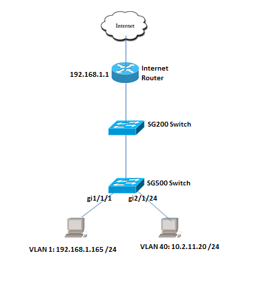
We have existing VLAN 1 - 192.168.1.X /24 and works fine. All workstation can connect to internet. I have added new VLAN 40 on SG500 switch but not getting internet connection.
Here is my config on the SG500 switch:
For VLAN:
switchd3d0b3#sh vlan
Vlan Name Ports Type Authorization
---- ----------------- --------------------------- ------------ -------------
1 1 gi1/1/1-48,te1/1/1-4, Default Required
gi2/1/1-48,te2/1/1-4,
gi3/1/1-48,te3/1/1-4,
gi4/1/1-48,te4/1/1-4,
gi5/1/1-48,te5/1/1-4,
gi6/1/1-48,te6/1/1-4,
gi7/1/1-48,te7/1/1-4,
gi8/1/1-48,te8/1/1-4,Po1-32
40 40 gi2/1/24,gi3/1/48 static Required
switchd3d0b3#sh ip int vlan 1
IP Address Type Directed Precedence Status
Broadcast
------------------- ----------- ---------- ---------- -----------
192.168.1.250/24 Static disable No Valid
switchd3d0b3#sh ip int vlan 40
IP Address Type Directed Precedence Status
Broadcast
------------------- ----------- ---------- ---------- -----------
10.2.11.1/24 Static disable No Valid
From the SG500 switch i can ping the interface VLAN 1 and 40:
switchd3d0b3#ping 10.2.11.1
Pinging 10.2.11.1 with 18 bytes of data:
18 bytes from 10.2.11.1: icmp_seq=1. time=0 ms
18 bytes from 10.2.11.1: icmp_seq=2. time=0 ms
18 bytes from 10.2.11.1: icmp_seq=3. time=0 ms
18 bytes from 10.2.11.1: icmp_seq=4. time=0 ms
switchd3d0b3#ping 192.168.1.1
Pinging 192.168.1.1 with 18 bytes of data:
18 bytes from 192.168.1.1: icmp_seq=1. time=0 ms
18 bytes from 192.168.1.1: icmp_seq=2. time=0 ms
18 bytes from 192.168.1.1: icmp_seq=3. time=0 ms
18 bytes from 192.168.1.1: icmp_seq=4. time=0 ms
From SG500 switch can ping the IP address of the PC on VLAN 1 - 192.168.1.165
switchd3d0b3#ping 192.168.1.165
Pinging 192.168.1.165 with 18 bytes of data:
18 bytes from 192.168.1.165: icmp_seq=1. time=0 ms
18 bytes from 192.168.1.165: icmp_seq=2. time=0 ms
18 bytes from 192.168.1.165: icmp_seq=3. time=0 ms
18 bytes from 192.168.1.165: icmp_seq=4. time=0 ms
But cannot ping the IP address of the PC on VLAN 40 - 10.2.11.20
switchd3d0b3#ping 10.2.11.20
Pinging 10.2.11.20 with 18 bytes of data:
PING: no reply from 10.2.11.20
PING: timeout
PING: no reply from 10.2.11.20
PING: timeout
PING: no reply from 10.2.11.20
PING: timeout
PING: no reply from 10.2.11.20
PING: timeout
No internet access on PC on VLAN 40.
I assigned IP static address on the PC:
IP- 10.2.11.20
Subnet - 255.255.255.0
GW - 10.2.11.1
DNS IP address is same as on VLAN 1 workstations that have internet.
IP routing is enabled on the SG500 switch. What need to be checked?
Thank you.
Solved! Go to Solution.
- Labels:
-
LAN Switching
Accepted Solutions
")
")
- Mark as New
- Bookmark
- Subscribe
- Mute
- Subscribe to RSS Feed
- Permalink
- Report Inappropriate Content
01-25-2017 05:48 AM
Hi no you don't need a sub interface , create vlan 40 interface on the router and as Paul noted make sure the vlan is trunked and allowed on the layer 2 trunk interfaces back to through switches that's it , I cant see from your output which of the fastethernet interfaces are set to trunk , make sure the vlan is set at layer 2 as well in the database , if you only have vlan 1 currently you may need to make a trunk connection between your switches
interface fx
description trunk
switchport
switchport mode trunk
switchport trunk encapsulation dot1q
switchport trunk allowed vlan 1,40
show int trunk..... will tell you
This would be to create the vlan at layer 2
vlan 40
name xxxxx
Then create it at layer 3 and add the nat inside so it can break out
interface Vlan40
description
ip address x.x.x.x 255.255.255.0
ip nat inside
ip virtual-reassembly in
- Mark as New
- Bookmark
- Subscribe
- Mute
- Subscribe to RSS Feed
- Permalink
- Report Inappropriate Content
01-25-2017 03:01 AM
Hi
check the vlan interface you probably need to allow ip nat inside to the interface same as your other vlan interfaces so they can break out from private ip to public ip in translation
It will be on the router though as that's the internet facing device where NAT would be enabled , if there is not vlan interface it may be a sub-interface requires the ip nat inside for that vlan 40 subnet
if you cant see it post the config off the router take a look
- Mark as New
- Bookmark
- Subscribe
- Mute
- Subscribe to RSS Feed
- Permalink
- Report Inappropriate Content
01-25-2017 05:45 AM
Hi,
I have this config on the router. I masked the Public IP for security reasons.
interface FastEthernet4
description ***To Internet***
ip address 123.1.2.3 255.255.255.252
ip nat outside
ip virtual-reassembly in
duplex auto
speed auto
!
interface Vlan1
description ***Local Network***
ip address 192.168.1.1 255.255.255.0
ip nat inside
ip virtual-reassembly in
!
ip forward-protocol nd
no ip http server
no ip http secure-server
!
!
--More--
ip nat inside source list 1 interface FastEthernet4 overload
ip route 0.0.0.0 0.0.0.0 123.1.2.2 255.255.255.252
!
!
access-list 1 permit 192.168.1.0 0.0.0.255
!
control-plane
!
!
mgcp behavior rsip-range tgcp-only
mgcp behavior comedia-role none
mgcp behavior comedia-check-media-src disable
mgcp behavior comedia-sdp-force disable
!
mgcp profile default
Router#sh ip int br
Interface IP-Address OK? Method Status Protocol
FastEthernet0 unassigned YES unset up up
FastEthernet1 unassigned YES unset up down
FastEthernet2 unassigned YES unset up down
FastEthernet3 unassigned YES unset down down
FastEthernet4 123.1.2.3 YES NVRAM up up
NVI0 123.1.2.3 YES unset up up
Vlan1 192.168.1.1 YES NVRAM up up
Router#sh ip route
Codes: L - local, C - connected, S - static, R - RIP, M - mobile, B - BGP
D - EIGRP, EX - EIGRP external, O - OSPF, IA - OSPF inter area
N1 - OSPF NSSA external type 1, N2 - OSPF NSSA external type 2
E1 - OSPF external type 1, E2 - OSPF external type 2
i - IS-IS, su - IS-IS summary, L1 - IS-IS level-1, L2 - IS-IS level-2
ia - IS-IS inter area, * - candidate default, U - per-user static route
o - ODR, P - periodic downloaded static route, H - NHRP, l - LISP
a - application route
+ - replicated route, % - next hop override
Gateway of last resort is 123.1.2.2 to network 0.0.0.0
S* 0.0.0.0/0 [1/0] via 123.1.2.2
37.0.0.0/8 is variably subnetted, 2 subnets, 2 masks
C 123.1.2.1/30 is directly connected, FastEthernet4
L 123.1.2.3/32 is directly connected, FastEthernet4
192.168.1.0/24 is variably subnetted, 2 subnets, 2 masks
C 192.168.1.0/24 is directly connected, Vlan1
L 192.168.1.1/32 is directly connected, Vlan1
So i need to create a sub-interface on the router?
Thank you for your help.
- Mark as New
- Bookmark
- Subscribe
- Mute
- Subscribe to RSS Feed
- Permalink
- Report Inappropriate Content
01-25-2017 05:48 AM
Hi no you don't need a sub interface , create vlan 40 interface on the router and as Paul noted make sure the vlan is trunked and allowed on the layer 2 trunk interfaces back to through switches that's it , I cant see from your output which of the fastethernet interfaces are set to trunk , make sure the vlan is set at layer 2 as well in the database , if you only have vlan 1 currently you may need to make a trunk connection between your switches
interface fx
description trunk
switchport
switchport mode trunk
switchport trunk encapsulation dot1q
switchport trunk allowed vlan 1,40
show int trunk..... will tell you
This would be to create the vlan at layer 2
vlan 40
name xxxxx
Then create it at layer 3 and add the nat inside so it can break out
interface Vlan40
description
ip address x.x.x.x 255.255.255.0
ip nat inside
ip virtual-reassembly in
- Mark as New
- Bookmark
- Subscribe
- Mute
- Subscribe to RSS Feed
- Permalink
- Report Inappropriate Content
01-25-2017 05:55 AM
Hello
Just like to add-
Dont forget to amend the acl also for the NAT!
access-list 1 permit 10.2.11.0 0.0.0.255
res
Paul
Please rate and mark as an accepted solution if you have found any of the information provided useful.
This then could assist others on these forums to find a valuable answer and broadens the community’s global network.
Kind Regards
Paul
- Mark as New
- Bookmark
- Subscribe
- Mute
- Subscribe to RSS Feed
- Permalink
- Report Inappropriate Content
01-25-2017 06:37 AM
Hi,
I have configured the router as suggested:
interface Vlan40
ip address 10.2.11.254 255.255.255.0
ip nat inside
ip virtual-reassembly in
access-list 1 permit 192.168.1.0 0.0.0.255
access-list 1 permit 10.2.11.0 0.0.0.255
VLAN40 is showing down:
Router#sh ip int br
Interface IP-Address OK? Method Status Protocol
FastEthernet0 unassigned YES unset up up
FastEthernet1 unassigned YES unset up down
FastEthernet2 unassigned YES unset up down
FastEthernet3 unassigned YES unset down down
FastEthernet4 123.1.2.3 YES NVRAM up up
NVI0 123.1.2.3 YES unset up up
Vlan1 192.168.1.1 YES NVRAM up up
Vlan40 10.2.11.254 YES manual down down
Router#sh int vlan 40
Vlan40 is down, line protocol is down
Hardware is EtherSVI, address is 843d.c636.69f8 (bia 843d.c636.69f8)
Internet address is 10.2.11.254/24
MTU 1500 bytes, BW 100000 Kbit/sec, DLY 100 usec,
reliability 255/255, txload 1/255, rxload 1/255
Encapsulation ARPA, loopback not set
Keepalive not supported
ARP type: ARPA, ARP Timeout 04:00:00
Last input never, output never, output hang never
Last clearing of "show interface" counters never
Input queue: 0/75/0/0 (size/max/drops/flushes); Total output drops: 0
Queueing strategy: fifo
Output queue: 0/40 (size/max)
5 minute input rate 0 bits/sec, 0 packets/sec
5 minute output rate 0 bits/sec, 0 packets/sec
0 packets input, 0 bytes, 0 no buffer
Received 0 broadcasts (0 IP multicasts)
0 runts, 0 giants, 0 throttles
0 input errors, 0 CRC, 0 frame, 0 overrun, 0 ignored
0 packets output, 0 bytes, 0 underruns
0 output errors, 1 interface resets
0 unknown protocol drops
0 output buffer failures, 0 output buffers swapped out
Also, on the SG200 i connect my PC on a port member as VLAN40.
SG200 port GE48 is configured as trunk and connected to the router.

I set a static ip on my PC
IP: 10.2.11.2/24
GW: 10.2.11.254
Still no internet.
- Mark as New
- Bookmark
- Subscribe
- Mute
- Subscribe to RSS Feed
- Permalink
- Report Inappropriate Content
01-25-2017 07:27 AM
ok lets work back from your router , your vlan is down/down at layer 3 so somethings not right
do you have a spare port on the router to connect your laptop direct ?
if you do set the port as
interface f x
switchport mode access
switchport access vlan 40
..............
This should bring the vlan up/up and then test the internet from the router for that vlan
ping 8.8.8.8 source int vlan 40
can you also post the show int trunk off the router please as it is now
- Mark as New
- Bookmark
- Subscribe
- Mute
- Subscribe to RSS Feed
- Permalink
- Report Inappropriate Content
01-25-2017 08:20 AM
Hi,
I have spare port and i configured as what you suggested and VLAN 40 went up/up and on the PC connected to the switch port member on VLAN 40 i can access the internet. However VLAN 1 is down and all workstation on VLAN 1 don't have internet access anymore.
So i revert back because VLAN 1 is on production.
what need to check?
- Mark as New
- Bookmark
- Subscribe
- Mute
- Subscribe to RSS Feed
- Permalink
- Report Inappropriate Content
01-25-2017 08:31 AM
Hi Mark,
when i did "show int trunk" there is no output.
Thanks.
- Mark as New
- Bookmark
- Subscribe
- Mute
- Subscribe to RSS Feed
- Permalink
- Report Inappropriate Content
01-25-2017 10:00 AM
Hi Mark,
I have configured the router
interface f0
description trunk
switchport mode trunk
switchport trunk encapsulation dot1q
switchport trunk allowed vlan all
Router#sh interfaces trunk
Port Mode Encapsulation Status Native vlan
Fa0 on 802.1q trunking 1
Port Vlans allowed on trunk
Fa0 1-4094
Port Vlans allowed and active in management domain
Fa0 1,40
Port Vlans in spanning tree forwarding state and not pruned
Fa0 1,40
The VLAN went up/up now:
Router #sh ip int br
Interface IP-Address OK? Method Status Protocol
FastEthernet0 unassigned YES unset up up
FastEthernet1 unassigned YES unset up down
FastEthernet2 unassigned YES unset up down
FastEthernet3 unassigned YES unset up down
FastEthernet4 123.1.2.3 YES NVRAM up up
NVI0 123.1.2.3 YES unset up up
Vlan1 192.168.1.1 YES NVRAM up up
Vlan40 10.2.11.254 YES NVRAM up up
I can ping the DNS - 8.8.8.8 on router on VLAN 40:
Router#ping 8.8.8.8 source vlan 40
Type escape sequence to abort.
Sending 5, 100-byte ICMP Echos to 8.8.8.8, timeout is 2 seconds:
Packet sent with a source address of 10.2.11.254
!!!!!
I have this DHCP pool on the router:
ip dhcp pool LAN
network 192.168.1.0 255.255.255.0
dns-server 8.8.8.8
default-router 192.168.1.1
!
ip dhcp pool VLAN40
network 10.2.11.0 255.255.255.0
dns-server 8.8.8.8
default-router 10.2.11.254
Then i connected my PC on SG200 port GE24 which member on VLAN 40 but i can obtain IP address on VLAN1 - 192.168.1.X and not on VLAN40 - 10.2.11.X.
Thank you for helping. What i need to check?
- Mark as New
- Bookmark
- Subscribe
- Mute
- Subscribe to RSS Feed
- Permalink
- Report Inappropriate Content
01-26-2017 01:19 AM
ok cool so now you have internet on vlan 40 if you can ping google dns , so the router side is working
now I don't use these SMB switches at all I use catalyst cli only , the trunk looks correct on the router side allowing vlan 1 and 40 , so the far end of it on the switch must be too as they have to match
what way is the port set on the sg200 where your pc is , if you set static does it work ok ? is the port set as access ?
- Mark as New
- Bookmark
- Subscribe
- Mute
- Subscribe to RSS Feed
- Permalink
- Report Inappropriate Content
01-26-2017 01:59 AM
Hi Mark,
If i set the PC with static IP and DNS within VLAN 40 (10.2.11.x) i don't have internet access. But if i set to DHCP i will have internet access but the IP that I obtained is 192.168.1.X which is on VLAN 1. My PC is connected to SG200 port GE24 which is member of VLAN40 configured as trunk. Changing to access mode still same problem.
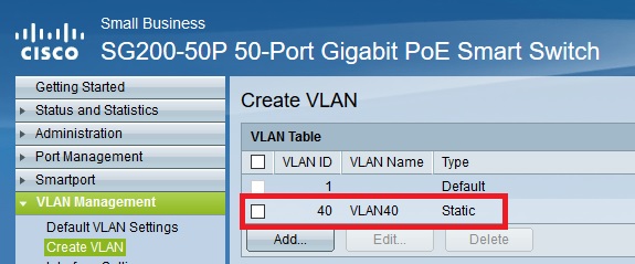
This is how the SG200 configured. See screenshots:
1. Add VLAN 40 on the switch.
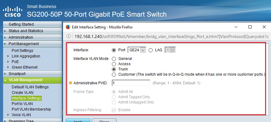
2. Interface GE24 port configuration:
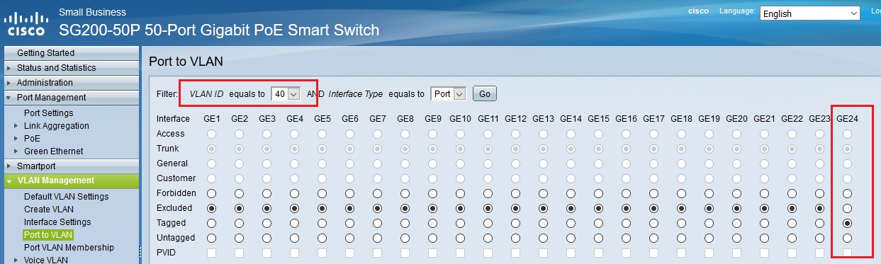
3. Member port GE24 tagged to VLAN 40
Thank you so much for helping me out.
regards,
Sy
- Mark as New
- Bookmark
- Subscribe
- Mute
- Subscribe to RSS Feed
- Permalink
- Report Inappropriate Content
01-26-2017 04:50 AM
Hi
im looking at the docs here as im not familiar with these gui switches, what you have looks right , I see one extra section in the docs below the port vlan membership table , is the vlan added to the port in that section ?
http://sbkb.cisco.com/CiscoSB/GetArticle.aspx?docid=67844b99e2da4a7f88db0c588197487d_Creating_VLANs_on_Cisco_Managed_Switches.xml&pid=2&converted=0
- Mark as New
- Bookmark
- Subscribe
- Mute
- Subscribe to RSS Feed
- Permalink
- Report Inappropriate Content
01-26-2017 05:59 AM
Hi Mark,
I can see the VLAN is added on the port.
VLAN1 - Untagged
VLAN40 - Tagged
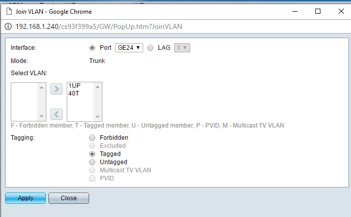

Thanks.
- Mark as New
- Bookmark
- Subscribe
- Mute
- Subscribe to RSS Feed
- Permalink
- Report Inappropriate Content
01-26-2017 06:22 AM
Discover and save your favorite ideas. Come back to expert answers, step-by-step guides, recent topics, and more.
New here? Get started with these tips. How to use Community New member guide