- Cisco Community
- Technology and Support
- Networking
- Switching
- MartinYou wouldn't normally
- Subscribe to RSS Feed
- Mark Topic as New
- Mark Topic as Read
- Float this Topic for Current User
- Bookmark
- Subscribe
- Mute
- Printer Friendly Page
- Mark as New
- Bookmark
- Subscribe
- Mute
- Subscribe to RSS Feed
- Permalink
- Report Inappropriate Content
01-31-2015 07:26 AM - edited 03-07-2019 10:27 PM
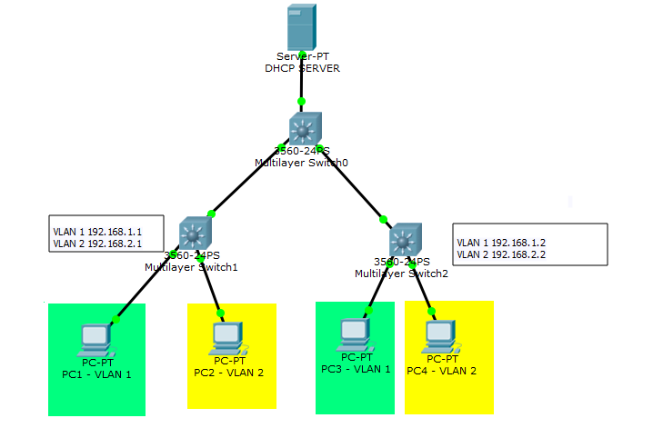
The attached diagram shows multiple L3 switches with one DHCP server. If the PCs were being configured manually, PC1-VLAN1 would be given a default gateway of 192.168.1.1, while PC3-VLAN1 would be given a default gateway of 192.168.1.2. However, how can this be done using DHCP with one DHCP server on the network?
I fully understand IP helper. The question is not how to get an appropriate vlan address from a DHCP pool but how to get an appropriate default gateway based on the L3 switch that the client is connected to.
Thanks for any help
Solved! Go to Solution.
- Labels:
-
Other Switching
Accepted Solutions
- Mark as New
- Bookmark
- Subscribe
- Mute
- Subscribe to RSS Feed
- Permalink
- Report Inappropriate Content
01-31-2015 10:01 AM
Martin
So looking at my diagram, if PC3 wants to connect to PC4, wouldn't it be better if multilayer switch 2 could do the routing rather than passing it up to the top switch?
Yes it would if there is a lot of traffic between those users.
But this a limitation of routing at the access layer, if you do this you cannot have the same vlan or more specifically the same IP subnet on two switches that are not interconnected because you cannot route to the same vlan.
This is a large subject that touches on a lot of design aspects so i'll cover a few things and if you want to discuss further then I'm perfectly happy.
The following is assuming a one IP subnet per vlan relationship. When I refer to having a vlan on single or multiple switches it is really to do with using the same IP subnet on multiple switches but because there is a direct mapping I have used the term vlan.
If you have a campus site with multiple buildings you would most certainly would have more than one L3 switch. In fact you would have a pair of L3 distribution switches per building that all the access switches in that building connected to.
The distribution switches would then connect via L3 routed links to core switches which would be housed in one of the main buildings in the campus. Note this building would also have it's own distribution pair of switches as well ie. nothing connects to the core other than distribution switches.
The question then becomes within each building do you connect your access switches via L2 links (trunks or access ports) or by L3 links.
If you use L3 links you cannot as I said have the same vlan across multiple switches in the same building. This is one of the main limitations of using L3 from the access layer.
The main advantages compared to a traditional L2 setup was that both uplinks could be used because STP did not block per vlan and you were also not reliant on STP to unblock links.
If you did need to have a vlan on multiple access switches you needed L2 uplinks to the distribution pair. If you needed the vlan across multiple buildings you would need separate links to the core or make your existing links L2 but you really don't want to do this.
So a lot of designs used L2 from the access layer and then routed the vlans on the distribution pair for flexibility but that meant STP was an issue.
This could be alleviated by using a L3 link between your distribution switches so there was no STP loop but again that meant you could only have vlans on single switches.
The main difference between that setup and L3 from the access layer was that with the above you should not span a vlan but you could as long as you accepted STP would block links, whereas with L3 you simply can't have the same vlan on multiple switches.
Now with stacked switches, VSS (and vPC although that is used more in DCs) you can run L2 from the access layer to a pair of switches that appear as one logical switch so a lot of the above considerations do not apply ie. STP does not block because the connections from an access layer switch to both distribution switches are seen as one logical link.
Which means you get the flexibility of L2 without the limitations but you would still connect your distribution switches to the core with L3.
So the above is a very condensed explanation of the types of design and where we are now in terms of what you can and can't do.
I have dealt with the campus environment ie. multiple buildings but the same applies to a single building but you might just have one pair of switches acting as both the core and distribution.
Going back you your diagram the main issue is obviously the same vlans on different switches but also you only in effect have one distribution switch.
So what you are trying to do can't really be done.
I hope I haven't confused the issue and like I say if you have any more queries or need more clarification please feel free to ask.
Jon
- Mark as New
- Bookmark
- Subscribe
- Mute
- Subscribe to RSS Feed
- Permalink
- Report Inappropriate Content
01-31-2015 08:07 AM
Martin
What are the connections from the bottom switches to the top switch ie. are they L2 trunk links or are they L3 routed links ?
Jon
- Mark as New
- Bookmark
- Subscribe
- Mute
- Subscribe to RSS Feed
- Permalink
- Report Inappropriate Content
01-31-2015 08:14 AM
Martin
You wouldn't normally try to do it this way.
The bottom switches would be access switches so the routing between vlans would be done on the top switch.
If you are routing on the access switch, as you are, then you don't have the same vlan on multiple access switches.
Jon
- Mark as New
- Bookmark
- Subscribe
- Mute
- Subscribe to RSS Feed
- Permalink
- Report Inappropriate Content
01-31-2015 09:19 AM
Thanks for your reply Jon. I accept that the routing could be done on the top switch and replace the bottom switches with L2 switches. But in another way this is my point. Should you only have one L3 switch in a network?
Suppose you have a large campus network with many vlans. You could have, for instance, one vlan that exits in many of the campus' different buildings. If a user on vlan1 and needs to connect to another user on the same floor but who is on a different vlan, then wouldn't it be better for the local L3 switch to do the routing rather than having to pass the traffic all the way up to the backbone core switch and back again? So looking at my diagram, if PC3 wants to connect to PC4, wouldn't it be better if multilayer switch 2 could do the routing rather than passing it up to the top switch?
Martin.
- Mark as New
- Bookmark
- Subscribe
- Mute
- Subscribe to RSS Feed
- Permalink
- Report Inappropriate Content
01-31-2015 10:01 AM
Martin
So looking at my diagram, if PC3 wants to connect to PC4, wouldn't it be better if multilayer switch 2 could do the routing rather than passing it up to the top switch?
Yes it would if there is a lot of traffic between those users.
But this a limitation of routing at the access layer, if you do this you cannot have the same vlan or more specifically the same IP subnet on two switches that are not interconnected because you cannot route to the same vlan.
This is a large subject that touches on a lot of design aspects so i'll cover a few things and if you want to discuss further then I'm perfectly happy.
The following is assuming a one IP subnet per vlan relationship. When I refer to having a vlan on single or multiple switches it is really to do with using the same IP subnet on multiple switches but because there is a direct mapping I have used the term vlan.
If you have a campus site with multiple buildings you would most certainly would have more than one L3 switch. In fact you would have a pair of L3 distribution switches per building that all the access switches in that building connected to.
The distribution switches would then connect via L3 routed links to core switches which would be housed in one of the main buildings in the campus. Note this building would also have it's own distribution pair of switches as well ie. nothing connects to the core other than distribution switches.
The question then becomes within each building do you connect your access switches via L2 links (trunks or access ports) or by L3 links.
If you use L3 links you cannot as I said have the same vlan across multiple switches in the same building. This is one of the main limitations of using L3 from the access layer.
The main advantages compared to a traditional L2 setup was that both uplinks could be used because STP did not block per vlan and you were also not reliant on STP to unblock links.
If you did need to have a vlan on multiple access switches you needed L2 uplinks to the distribution pair. If you needed the vlan across multiple buildings you would need separate links to the core or make your existing links L2 but you really don't want to do this.
So a lot of designs used L2 from the access layer and then routed the vlans on the distribution pair for flexibility but that meant STP was an issue.
This could be alleviated by using a L3 link between your distribution switches so there was no STP loop but again that meant you could only have vlans on single switches.
The main difference between that setup and L3 from the access layer was that with the above you should not span a vlan but you could as long as you accepted STP would block links, whereas with L3 you simply can't have the same vlan on multiple switches.
Now with stacked switches, VSS (and vPC although that is used more in DCs) you can run L2 from the access layer to a pair of switches that appear as one logical switch so a lot of the above considerations do not apply ie. STP does not block because the connections from an access layer switch to both distribution switches are seen as one logical link.
Which means you get the flexibility of L2 without the limitations but you would still connect your distribution switches to the core with L3.
So the above is a very condensed explanation of the types of design and where we are now in terms of what you can and can't do.
I have dealt with the campus environment ie. multiple buildings but the same applies to a single building but you might just have one pair of switches acting as both the core and distribution.
Going back you your diagram the main issue is obviously the same vlans on different switches but also you only in effect have one distribution switch.
So what you are trying to do can't really be done.
I hope I haven't confused the issue and like I say if you have any more queries or need more clarification please feel free to ask.
Jon
- Mark as New
- Bookmark
- Subscribe
- Mute
- Subscribe to RSS Feed
- Permalink
- Report Inappropriate Content
12-11-2021 08:21 AM
Hi Jon,
when you say "This could be alleviated by using a L3 link between your distribution switches so there was no STP loop but again that meant you could only have vlans on single switches" are you reffering to the Martin's topology or do you mean in general?
One more thing I wanted to discuss with you. For example, there is a VLAN/subnet with 10.10.10.0/24. VLAN users are connected to layer 3 switch A and B.
Is it possible to have default gateway at SVI on switch A at 10.10.10.1, and at SVI on switch B at 10.10.10.40?
- Mark as New
- Bookmark
- Subscribe
- Mute
- Subscribe to RSS Feed
- Permalink
- Report Inappropriate Content
12-11-2021 10:11 AM
There are a few things in your question that are not clear. What is the connection between switch A and switch B? Is it an access port on each switch in the vlan that has subnet 10.10.10.0? Or a trunk carrying several vlans, including the vlan that has subnet 10.10.10.0? The important thing is whether there is a single broadcast domain including both switches so that a device in that vlan/subnet on switch A can receive an arp request from a device in that vlan/subnet on switch B and respond to it (and both devices would communicate directly/locally without needing any layer 3 routing).
If you want to have default gateway of 10.10.10.1 on one switch and default gateway of 10.10.10.40 on the other I would suggest this approach - configure 2 HSRP groups on the switch vlan interfaces. One HSRP group would specify 10.10.10.1 as the gateway and switch A would have higher priority and switch B lower priority for this group. The other HSRP group would specify 10.10.10.40 as the gateway and switch B would have higher priority and switch A lower priority for this group. The challenge in this would be how to get one group of hosts to select 10.10.10.1 and the other group of clients to select 10.10.10.40?
Rick
- Mark as New
- Bookmark
- Subscribe
- Mute
- Subscribe to RSS Feed
- Permalink
- Report Inappropriate Content
12-11-2021 10:24 AM - edited 12-11-2021 10:31 AM
There is IP routing between switches. The link is in different subnet.
If I understood you correctly, it is possible to have multiple default gateways per VLAN/subnet?
- Mark as New
- Bookmark
- Subscribe
- Mute
- Subscribe to RSS Feed
- Permalink
- Report Inappropriate Content
12-11-2021 10:45 AM
Yes it is possible to have multiple default gateways per vlan/subnet. But certain conditions must be satisfied if it is to work correctly. One of those conditions is that all hosts in the same subnet must be in the same broadcast domain and able to communicate with each other locally (without needing layer 3 routing).
If I am understanding correctly what you describe it is like this:
vlan with subnet 10.10.10.0 is connected to switch A on some interface(s).
switch A connects to switch B on some other subnet.
vlan with subnet 10.10.10.0 is connected to switch B on some interface(s).
That will create problems.
Rick
- Mark as New
- Bookmark
- Subscribe
- Mute
- Subscribe to RSS Feed
- Permalink
- Report Inappropriate Content
02-08-2015 12:41 AM
Thanks Jon for you're well explained answer. It all makes sense.
Martin.
Discover and save your favorite ideas. Come back to expert answers, step-by-step guides, recent topics, and more.
New here? Get started with these tips. How to use Community New member guide