- Cisco Community
- Technology and Support
- Networking
- Switching
- Transit vlan to router from layer 3 switch
- Subscribe to RSS Feed
- Mark Topic as New
- Mark Topic as Read
- Float this Topic for Current User
- Bookmark
- Subscribe
- Mute
- Printer Friendly Page
- Mark as New
- Bookmark
- Subscribe
- Mute
- Subscribe to RSS Feed
- Permalink
- Report Inappropriate Content
10-02-2018 07:29 AM - edited 03-08-2019 04:17 PM
I can use some assistance with this since I've not created anything like this before. I have 5 switches, 1 Cisco Catalyst 9300 and 4 Meraki MS225-48FP's. The meraki's are our LAN switches that are on 4 different floors. In the attached image B2SW01 is on the 6th floor with a fiber run to B2SW04 which is on the 1st floor. Switches B2SW02 & B2SW03 are on the 2nd and 3rd floor and connect to B2SW04. From the B2SW04 we are connected to our internet router.
The Cisco 9300 switch is on the 6th floor with a connection to B2SW01. It is at the top of a new server rack supporting UCS-Mini. We want to implement vlans for our network and have been advised that the Cisco switch would be the best solution. It is suggested that we create a static route on the 9300 to the router and the vlans would use that for connecting to the internet.
The question I have is can we do that when we don't have a direct connection between the 9300 and the router? Is it as simple as creating the transit vlan and then tagging the port on B2SW04 that is connected to the router to only allow traffic from the transit vlan?
We are trying to avoid a new run from the 6th floor to the 1st floor for now. Our 2019 plans will be to move the router and internet connection to the 6th floor and also add redundant connection between the meraki switches. Thanks in advance for suggestions and assistance.
Solved! Go to Solution.
- Labels:
-
LAN Switching
Accepted Solutions
- Mark as New
- Bookmark
- Subscribe
- Mute
- Subscribe to RSS Feed
- Permalink
- Report Inappropriate Content
10-24-2018 11:23 AM
Thanks for everyone's input. Issue has been resolve with some work from our firewall provider
- Mark as New
- Bookmark
- Subscribe
- Mute
- Subscribe to RSS Feed
- Permalink
- Report Inappropriate Content
10-02-2018 11:14 AM
Your verbal description says that your Meraki switch B2SW04 connects to your Internet router. But your diagram shows it connecting to a Cisco switch. Which is correct?
Your description of the environment does not indicate where routing for the LAN vlans is being done. Is it done in the Meraki switches? Being done in the Cisco switch? Being done on the router? Can you clarify?
It looks like vlan 1 is being used as a management vlan. But it also describes vlan 1 as a transit vlan which suggests that data traffic is combined with management traffic. Is this correct?
You describe the 9300 switch as a top of rack and seem to indicate that new vlans will be defined for the servers and their traffic in this rack. Is this correct?
You do not indicate where you want routing for these new vlans to be done. Do you want this routing to be done on the 9300? On the existing switch? On the router?
Without knowing answers to these things it is difficult to give good advice. We can certainly say that one approach could be to do routing for these new vlans on the 9300 and to configure a new vlan connecting 9300 through the other switches to the router. A variation on this approach would be to do routing for the new vlans on the 9300 and to use vlan 1 as a transit vlan to get data back and forth to the Internet router. Another alternative could be to configure the connection from 9300 to Meraki as a trunk (assuming that connections between Meraki switches is also a trunk), and to extend the vlans to wherever you want routing to occur.
HTH
Rick
Rick
- Mark as New
- Bookmark
- Subscribe
- Mute
- Subscribe to RSS Feed
- Permalink
- Report Inappropriate Content
10-02-2018 12:43 PM
Sorry for the confusion. The drawing is a topology recommendation which I should have clarified at the beginning. I've attached a new image that shows our layout.
The recommendation is for the Cisco 9300 to serve as our vlan switch and perform the vlan routing for the meraki switches. There is only a single connection from the 1st floor closet where B2SW04 is located to the 6th floor where it connects to B2SW01. Our router is on the 1st floor and connected to B2SW04. We do not want it configure our vlans on the router. It is due to be replaced in 2019 and we'll be moving to a different solution.
We considered vlan's on the Meraki but the Cisco was recommended as a better solution. With only one network drop from the 1st floor to the 6th we cannot connect the Cisco to the router but we could connect the B2SW04 switch to the Cisco switch instead of the B2SW01 switch without any issue.
So basically we will have the Cisco serve as our vlan switch. We need to establish connection to the router. We could use the default vlan1 for this static connection or create a new vlan for this propose, whichever make the most since.
- Mark as New
- Bookmark
- Subscribe
- Mute
- Subscribe to RSS Feed
- Permalink
- Report Inappropriate Content
10-03-2018 01:40 AM - edited 10-03-2018 01:41 AM
Use a new vlan just for the connectivity between the 9300 and the router.
On the interconnect between the 9300, B2SW01 and B2SW04 assuming they are trunks just add that vlan (unless you are allowing all vlans anyway).
On B2SW04 make the port that connects to the router an access port in that vlan.
Jon
- Mark as New
- Bookmark
- Subscribe
- Mute
- Subscribe to RSS Feed
- Permalink
- Report Inappropriate Content
10-03-2018 08:51 AM
Thanks for the updated drawing. It does help clarify the topology. I am a bit confused. Your original drawing shows 6 subnets in the 172.17.0.0 network. This led me to assume that the existing Meraki switches were doing vlans and trunking. A recent response seems to suggest that the Meraki are not doing vlans. Can you clarify how the Meraki are configured and how they are operating with multiple subnets? What is currently routing between those subnets?
HTH
Rick
Rick
- Mark as New
- Bookmark
- Subscribe
- Mute
- Subscribe to RSS Feed
- Permalink
- Report Inappropriate Content
10-03-2018 08:57 AM
The Meraki's would remain as layer 2 switches. The vlans in the drawing are what we are moving to. Our current IP scope is 172.17.5.0/24. All end point are assigned a static IP. With the new vlans we want to split our endpoints up by device type or role such as servers, PC, Voip, etc. At this point nothing is doing any routing since we're creating the vlans. That is one of the key questions we have as we set the vlans up.
- Mark as New
- Bookmark
- Subscribe
- Mute
- Subscribe to RSS Feed
- Permalink
- Report Inappropriate Content
10-03-2018 09:22 AM
Thanks for the clarification. So in your current environment there is just a single vlan? Am I correct in assuming that when you add the 9300 and create multiple vlans that the Meraki switches will be configured with multiple vlans and some interfaces on the Meraki configured as trunks? If that is true then I mostly agree with the suggestion from Jon. You should create the vlans on Meraki and 9300. Connections between Meraki switches and between Meraki and 9300 should be configured as trunks and carry all the vlans. There should be another vlan created to be the transit vlan. The 9300 should be the default gateway for all network devices connected on the vlans. The 9300 should enable inter vlan routing and should have a default route with the Internet router as the next hop. The connection from the Meraki switch to the Internet router should carry the transit vlan. The router should have routes for all the network subnets with the 9300 as the next hop over the transit vlan. This routing could be done with static routes or you might consider using a dynamic routing protocol (especially if your future plans include providing some redundancy within your network). The one place I may be different from Jon is about the connection from Meraki to Internet router. He suggests that it be an access port in the transit vlan. I wonder if you would want to have a management vlan that is separate from the data vlans. If so then the connection to Internet router needs to be a trunk with only the transit vlan and the management vlan. If you do not intend to have a management vlan then I agree that the connection should be an access port.
HTH
Rick
Rick
- Mark as New
- Bookmark
- Subscribe
- Mute
- Subscribe to RSS Feed
- Permalink
- Report Inappropriate Content
10-03-2018 11:10 AM
I wouldn't define our current environment as a vlan. When the network was 1st setup unmanaged Dell switches were used. No work was ever done to define vlans and split the network up into smaller broadcast domain. The Meraki's were brought for that reason. We wanted visibility of our network and the ability to create vlans. The Cisco was purchased at the same time with it primary role of providing connectivity to a new Cisco UCS-Mini.
Are you suggesting that on both the Cisco and Meraki's I create identical L3 vlans? Not a problem to do that but I wanted to verify. It is my understanding that I would leave the Meraki's as layer 2 switches. Unlike the Cisco's you can't actually create a layer 2 vlan on the Meraki. Supposedly if you enter a number on the port for allowed vlans it creates a layer 2 vlan behind the scene.
One other note on the Meraki's. By default both platforms have a vlan1 and it was suggested this could create a conflict. During a upcoming maintenance window will change the native vlan from 1 to 2 on the meraki's.
- Mark as New
- Bookmark
- Subscribe
- Mute
- Subscribe to RSS Feed
- Permalink
- Report Inappropriate Content
10-03-2018 11:44 AM
Not sure what you mean by L3 vlans ?
If you mean L3 interfaces for the vlans then you only create these on the 9300.
On all switches you would need the L2 vlans and you would need to use trunks between all switches but I have not used Meraki so are you saying that is not possible ?
Jon
- Mark as New
- Bookmark
- Subscribe
- Mute
- Subscribe to RSS Feed
- Permalink
- Report Inappropriate Content
10-03-2018 12:01 PM
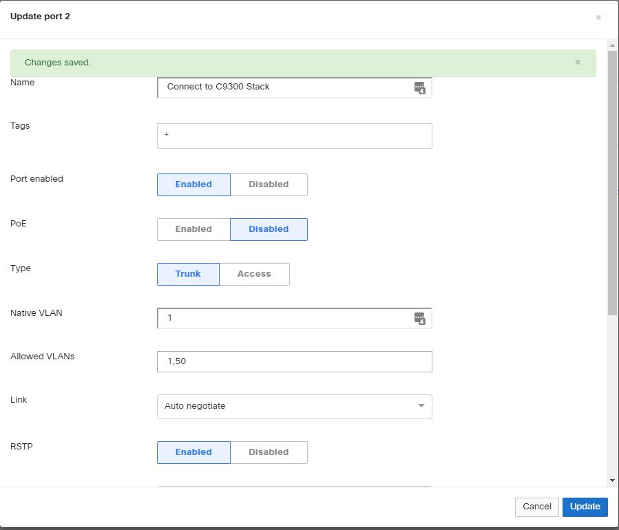
Meraki by default use layer 2 vlans but unlike the Cisco's you don't actually have a function to create the vlan and name it. When configuring a port on a meraki all vlans. I've attached two images showing the configuration of a meraki port. Default is set to allow all vlans. I then changed it to only vlan 50 and have an image now show 1,50 are the allowed vlans.
For L3 I was referring to Layer 3 vlans. It is my understanding that we need to setup layer 3 vlans if we're not using a router to route between the vlans. For our configuration the Cisco switch was the best option to create the layer 3 vlans.
- Mark as New
- Bookmark
- Subscribe
- Mute
- Subscribe to RSS Feed
- Permalink
- Report Inappropriate Content
10-03-2018 01:33 PM
I do not have experience with Meraki switches so my explanation of what to do was based on typical Cisco switches. You need to understand the functions I was describing and figure how to achieve it on the Meraki switches. I was not suggesting layer 3 vlans on Meraki. The layer 3 vlans would be on the 9300 and that is to be able to do inter vlan routing on the 9300. The Meraki switches need to assign access ports to appropriate vlans. The Meraki also needs to configure ports connecting the switches as trunk ports. The trunk ports between switches need to carry all of the local vlans (that will make the 172.17 subnets), the transit vlan, and perhaps a management vlan. If you want a management vlan then the port connecting Meraki to router would be a trunk and it would carry only the management vlan and the transit vlan. If there is not a management vlan then the port on Meraki connecting to router would be an access port in the transit vlan.
HTH
Rick
Rick
- Mark as New
- Bookmark
- Subscribe
- Mute
- Subscribe to RSS Feed
- Permalink
- Report Inappropriate Content
10-03-2018 01:51 PM
Thanks, I didn't think we would need to duplicate the layer vlans on the Meraki's. Even though the meraki's do not display layer 2 information like the Cisco can enter the van number for a port. Meraki has a dashboard that has a view of all the ports and the allowed vlan.
Thanks for your assistance. I've been working on creating the vlans on the 9300 and the only issue I have so far is getting the inter-vlan configuration set. Researching that information and hope to have it setup soon for testing.
- Mark as New
- Bookmark
- Subscribe
- Mute
- Subscribe to RSS Feed
- Permalink
- Report Inappropriate Content
10-03-2018 01:57 PM - edited 10-03-2018 02:01 PM
Just to clarify.
There is no such thing as a L3 vlan, because a vlan is a L2 concept.
If you mean by L3 vlan a L3 interface ("int vlan x") then yes you only need these on the 9300 but you need the vlans on all the other switches as well.
Jon
- Mark as New
- Bookmark
- Subscribe
- Mute
- Subscribe to RSS Feed
- Permalink
- Report Inappropriate Content
10-03-2018 02:34 PM
Thank you for the explanation.
- Mark as New
- Bookmark
- Subscribe
- Mute
- Subscribe to RSS Feed
- Permalink
- Report Inappropriate Content
10-04-2018 08:39 AM
I've setup the vlans on the Cisco 9300 but when I ping to test for inter-vlan routing it fails. I 1st tried from My PC which is connected to a meraki switch and fail. I then connected a laptop to the Cisco switch and same results.
Here's a sample for one of the vlans I created:
B2SRSW#conf t
Enter configuration commands, one per line. End with CNTL/Z.
B2SRSW(config)#vlan 160
B2SRSW(config-vlan)#name B2local
B2SRSW(config)#interface gigabitethernet 2/0/16
B2SRSW(config-if)#switchport mode trunk
B2SRSW(config-if)#switchport access vlan 160
B2SRSW(config-if)#end
B2SRSW#conf t
Enter configuration commands, one per line. End with CNTL/Z.
B2SRSW(config)#interface vlan 160
B2SRSW(config-if)#ip address 172.17.5.1 255.255.255.0
B2SRSW(config-if)#no shutdown
B2SRSW(config-if)#end
Here are the results of running Show ip route:
B2SRSW#show ip route
Codes: L - local, C - connected, S - static, R - RIP, M - mobile, B - BGP
D - EIGRP, EX - EIGRP external, O - OSPF, IA - OSPF inter area
N1 - OSPF NSSA external type 1, N2 - OSPF NSSA external type 2
E1 - OSPF external type 1, E2 - OSPF external type 2
i - IS-IS, su - IS-IS summary, L1 - IS-IS level-1, L2 - IS-IS level-2
ia - IS-IS inter area, * - candidate default, U - per-user static route
o - ODR, P - periodic downloaded static route, H - NHRP, l - LISP
a - application route
+ - replicated route, % - next hop override, p - overrides from PfR
Gateway of last resort is 0.0.0.0 to network 0.0.0.0
S* 0.0.0.0/0 is directly connected, Vlan50
172.16.0.0/16 is variably subnetted, 2 subnets, 2 masks
C 172.16.6.0/24 is directly connected, Vlan150
L 172.16.6.1/32 is directly connected, Vlan150
172.17.0.0/16 is variably subnetted, 14 subnets, 2 masks
C 172.17.0.0/24 is directly connected, Vlan1
L 172.17.0.1/32 is directly connected, Vlan1
C 172.17.1.0/24 is directly connected, Vlan101
L 172.17.1.1/32 is directly connected, Vlan101
C 172.17.2.0/24 is directly connected, Vlan110
L 172.17.2.1/32 is directly connected, Vlan110
C 172.17.3.0/24 is directly connected, Vlan120
L 172.17.3.1/32 is directly connected, Vlan120
C 172.17.4.0/24 is directly connected, Vlan130
L 172.17.4.1/32 is directly connected, Vlan130
C 172.17.5.0/24 is directly connected, Vlan160
L 172.17.5.1/32 is directly connected, Vlan160
C 172.17.6.0/24 is directly connected, Vlan140
L 172.17.6.1/32 is directly connected, Vlan140
192.168.1.0/24 is variably subnetted, 2 subnets, 2 masks
C 192.168.1.0/29 is directly connected, Vlan50
L 192.168.1.3/32 is directly connected, Vlan50
B2SRSW#
This is the interface connected to the meraki B2SW01 switch:
interface GigabitEthernet1/0/24
switchport mode trunk
spanning-tree portfast trunk
The meraki port is set as a trunk port.
Curious also why when running the show vlans command I get No Virtual LANs configured.
I've attached the result of show running-configuration if that will help
Discover and save your favorite ideas. Come back to expert answers, step-by-step guides, recent topics, and more.
New here? Get started with these tips. How to use Community New member guide