- Cisco Community
- Technology and Support
- Networking
- Switching
- Re: VSS on 4506e Failed
- Subscribe to RSS Feed
- Mark Topic as New
- Mark Topic as Read
- Float this Topic for Current User
- Bookmark
- Subscribe
- Mute
- Printer Friendly Page
- Mark as New
- Bookmark
- Subscribe
- Mute
- Subscribe to RSS Feed
- Permalink
- Report Inappropriate Content
08-10-2019 02:18 PM - edited 08-11-2019 12:48 AM
Hello Folks
Question 1)
So I configed a pair of 4506e with VSS and it was working fine after verification and everything, and I even had this template of Gig Y/x/x on one switch which Y is the Switch number and the other switch was in standby mode that had no access to any commands, so I saved the config, turned off both of 'em
next day I assume I did nothing but disconnecting one of the cables in between the pair to use the cable somewhere else,
after I turned them on again, not only they are not seeing each other but
on the switch number 2 with lower priority which used to be a standby switch, I can't even type the command switch or show switch anymore,
what can I do other than erasing the nvram? I have no access to command switch anywhere which is funny, neither privilege nor config mode
Question 2)
What is the best practice of connecting a stackwised(Distribution level) switch to a VSS switch, connect to both VSS pairs or to just one of 'em? what's the common practice in productions?, I think it doesn't matter that VSS is a one logical switch, you can still get a better performance when you access them both directly, right?
thx a lot
Solved! Go to Solution.
- Labels:
-
Catalyst 4000
Accepted Solutions
- Mark as New
- Bookmark
- Subscribe
- Mute
- Subscribe to RSS Feed
- Permalink
- Report Inappropriate Content
08-10-2019 04:48 PM
If you are sure physically connected VSL links as per your configuration, turn off the Switch 2 and connect console. power on and post the logs.
i am sure once it reboot it joined the VSS, by checking the config.
- Mark as New
- Bookmark
- Subscribe
- Mute
- Subscribe to RSS Feed
- Permalink
- Report Inappropriate Content
08-10-2019 06:05 PM
What happens if you connect the cables up and reboot the VSS pair?
- Mark as New
- Bookmark
- Subscribe
- Mute
- Subscribe to RSS Feed
- Permalink
- Report Inappropriate Content
08-11-2019 12:11 AM
If this is what you're trying to do, DON'T.
The correct boot variable is "boot system flash bootflash:filename.IOS" can only be set on switch 1.
If switch 2 has joined the VSS, set the boot variable string on switch 1 and this should be fine.
- Mark as New
- Bookmark
- Subscribe
- Mute
- Subscribe to RSS Feed
- Permalink
- Report Inappropriate Content
08-10-2019 02:48 PM
Question 1 :
As long as you have SVL Link connected each other - they should be able to form back VSS again.
keep that in mind,,,VSS means one control plan for both, you can issue any commands on standby.
Standby got active when the partner go down. if you like to standby to be active you need to issue command force switch over. from Active.
If you have removed the cable between the device, there is communication of both the chasis, then both become active / Active.
To solve your issue, restore the SVL cables - make sure both the side domain correct. and reboo the switch, so they can form VSS.
if you like to make them standalone you need to follow below steps :
Then proceed with the following commands:
Converting the VSS Active Switch to Standalone
When you convert the VSS active switch to standalone mode, the VSS active switch removes the provisioning and configuration information related to VSL links and the peer chassis modules, saves the configuration file, and performs a reload. The switch comes up in standalone mode with only the configuration data relevant to the standalone system.
The VSS standby switch of the VSS becomes VSS active. VSL links on this switch are down because the peer is now unavailable.
To convert the VSS active switch to standalone mode, perform this task on the VSS active switch:
|
Command
|
Purpose
|
|---|---|
|
Switch-1# switch convert mode stand-alone |
Converts Switch 1 to standalone mode. After you enter the command, you are prompted to confirm the action. Enter yes. |
Conversion from VSS to standalone causes all physical interfaces to be administratively shutdown and written to the startup-config. This is a safeguard against a standalone system arriving in the network alive and conflicting with a bridge or router MAC address, which might still be there if one of the VSS switches is still running in VSS mode.
We do not recommend that you convert a VSS to standalone in a live network.
Converting the VSS Standby Switch to Standalone
When you convert the new VSS active switch to standalone mode, the switch removes the provisioning and configuration information related to VSL links and the peer switch modules, saves the configuration file and performs a reload. The switch comes up in standalone mode with only its own provisioning and configuration data.
To convert the peer switch to standalone, perform this task on the VSS standby switch:
|
Command
|
Purpose
|
|---|---|
|
Switch-2# switch convert mode stand-alone |
Converts Switch 2 to standalone mode. After you enter the command, you are prompted to confirm the action. Enter yes.
|
Question 2 :
You want to connect to Stack to VSS , you can do Port-channle like below ( since VSS logically 1 switch)
3750 switch 1------ 4K switch 1
3750 switch 2------ 4K switch 2
- Mark as New
- Bookmark
- Subscribe
- Mute
- Subscribe to RSS Feed
- Permalink
- Report Inappropriate Content
08-10-2019 03:07 PM - edited 08-10-2019 03:10 PM
I restored both cables, but switches are not forming a port-channel anymore, none the less VSL
but the switch number 1(active switch) is still see the interfaces in this pattern Y/x/x which it means he thinks he is still active,
and when I console to switch number 2(used to be the standby switch) which I used to not have access to its command line because it was a standby switch, now I have access to its command because he is not participating int VSS anymore and interfaces pattern are x/x right now on it, but I can't issue these two commands on switch 2:
switch2# show switch .....
or
switch2(config)# switch ? ....
they don't exist
what am I missing?
- Mark as New
- Bookmark
- Subscribe
- Mute
- Subscribe to RSS Feed
- Permalink
- Report Inappropriate Content
08-10-2019 04:48 PM
If you are sure physically connected VSL links as per your configuration, turn off the Switch 2 and connect console. power on and post the logs.
i am sure once it reboot it joined the VSS, by checking the config.
- Mark as New
- Bookmark
- Subscribe
- Mute
- Subscribe to RSS Feed
- Permalink
- Report Inappropriate Content
08-10-2019 06:05 PM
What happens if you connect the cables up and reboot the VSS pair?
- Mark as New
- Bookmark
- Subscribe
- Mute
- Subscribe to RSS Feed
- Permalink
- Report Inappropriate Content
08-10-2019 08:29 PM - edited 08-10-2019 08:32 PM
Exactly, you guys figured it
Idk how it slipped through my fingers
the switch is booting with its older rom, even that I have confreg 0x2101, and I set the boot variable to the newer rom and did a wr before joining the VSS for the first time and honestly it changed my boot to the new image but after joining the VSS and working for a while, after another reboot it's reverted back to the older rom and it says boot variable does not exist.
I don't know why.
I use this rom
cat4500e-universalk9.SPA.03.08.07.E.152-4.E7
with Enterprise License
now I fixed everything(VSL is on) except that every time it boots it goes to ROMMON, and I have to manually boot it up
even though that I issued the command boot system flash bootflash:/cat4500e-universalk9.SPA.03.08.07.E.152-4.E7.bin
and I did another WR, and then I issued this command switch convert mode virtual and reload the switch which went right into rommon, so why is that?
why my configuration didn't take effect?
and now with limited access
Switch-standby>
Standby console disabled.
Valid commands are: exit, logout

Switch-standby>
Standby console disabled.
Valid commands are: exit, logout

Switch-standby>
Standby console disabled.
Valid commands are: exit, logout

Switch-standby>
how can I change the boot variable?
should I force to switch over to switch 2 as an active, change the boot var and switch back?
- Mark as New
- Bookmark
- Subscribe
- Mute
- Subscribe to RSS Feed
- Permalink
- Report Inappropriate Content
08-10-2019 10:21 PM - edited 08-10-2019 10:59 PM
@George-Sl wrote:
even that I have confreg 0x2101
Config registry 0x2101 means IGNORE boot variable string.
The correct boot variable string should be 0x2102.
- Mark as New
- Bookmark
- Subscribe
- Mute
- Subscribe to RSS Feed
- Permalink
- Report Inappropriate Content
08-10-2019 11:27 PM - edited 08-11-2019 12:34 AM
so I changed the bootvar, by forcing the switchover and I went to Switch 2 to do this(bootvar modification), how can we change the boot variable remotely?
- Mark as New
- Bookmark
- Subscribe
- Mute
- Subscribe to RSS Feed
- Permalink
- Report Inappropriate Content
08-11-2019 12:11 AM
If this is what you're trying to do, DON'T.
The correct boot variable is "boot system flash bootflash:filename.IOS" can only be set on switch 1.
If switch 2 has joined the VSS, set the boot variable string on switch 1 and this should be fine.
- Mark as New
- Bookmark
- Subscribe
- Mute
- Subscribe to RSS Feed
- Permalink
- Report Inappropriate Content
08-11-2019 12:26 AM - edited 08-11-2019 11:15 AM
1)
yes my mistake(but still it shouldn't have to go to rommon) but can you rationalize this for me a little bit, because the only difference in these two parameters is bootstrap, how can booting into bootstap ignore the bootvariable, I think bootstrap has to look for boot variable?!!
0x2101
- Boots into bootstrap
- Ignores break
- Boots into ROM if initial boot fails
- 9600 console baud rate
0x2102
- Ignores break
- Boots into ROM if initial boot fails
- 9600 console baud rate default value for most platforms
Bootstrap is more like BIOS. It will initialize the basic device drivers and
then will execute the IOS image. So, ideally, when the device is working in
good condition, the bootstrap will initialize the flash disk and then copy
the IOS into the RAM, and initialize IOS execution. If, for some reason, IOS
execution fails, then it will copy the ROM Monitor software into the RAM and
then execute that.
2)
could you answer my 3rd question in the original(first) post as well?
3)
I made a port channel with only two ports, one of 'em is on 3750 and the other one is on another 3750, both of the switches are stacked ofc,
the bundled port is being connected to both 4506e switches, the second I press the no shut on portchannel of 3750 master switch, I get this error(FYI after connecting the stackwise I didn't do any stackwise configuration, I think they are already stacked and fine)
*Mar  1 01:47:13.181: %LINK-3-UPDOWN: Interface FastEthernet1/0/1, changed state to down
*Mar  1 01:47:13.189: %LINK-3-UPDOWN: Interface FastEthernet3/0/1, changed state to down
*Mar  1 01:47:14.624: %EC-5-CANNOT_BUNDLE2: Fa3/0/1 is not compatible with Po2 and will be suspended (trunk mode of Fa3/0/1 is dynamic, Po2 is trunk)
*Mar  1 01:47:14.674: %EC-5-CANNOT_BUNDLE2: Fa1/0/1 is not compatible with Po2 and will be suspended (trunk mode of Fa1/0/1 is dynamic, Po2 is trunk) (SW2-1)
*Mar  1 01:47:16.629: %LINK-3-UPDOWN: Interface FastEthernet3/0/1, changed state to up
*Mar  1 01:47:16.679: %LINK-3-UPDOWN: Interface FastEthernet1/0/1, changed state to up
SW2#show switch detail
Switch/Stack Mac Address : 0817.3557.d780
                                           H/W   Current
Switch#  Role   Mac Address     Priority Version  State
----------------------------------------------------------
 1       Member 5897.1e08.e480     1      0       Ready
 2       Member e8ba.7048.6b80     1      0       Ready
*3       Master 0817.3557.d780     1      0       Ready

and yes I have 3 stack members but I am using only switch 3 and 1 for port channel :)

         Stack Port Status             Neighbors
Switch#  Port 1     Port 2           Port 1   Port 2
--------------------------------------------------------
  1        Ok        Down               3      None
  2       Down        Ok              None       3
  3        Ok         Ok                2        1

SW2#
SW2#show run
switch 1 provision ws-c3750v2-24ps
switch 2 provision ws-c3750v2-24ps
switch 3 provision ws-c3750v2-24ps
!
interface Port-channel2
switchport trunk encapsulation dot1q
switchport mode trunk
switchport nonegotiate
!
interface FastEthernet1/0/1
channel-group 2 mode on
!
.
.
!
interface FastEthernet3/0/1
channel-group 2 mode on
!
!
!
!
vstack
!

SW2#
SW2#show ip int br

Interface IP-Address OK? Method Status Protocol

FastEthernet1/0/1 unassigned YES unset up down

FastEthernet3/0/1 unassigned YES unset up down

Port-channel2 unassigned YES unset down down


SW2#show int status

Port Name Status Vlan Duplex Speed Type
Fa1/0/1 suspended 1 a-full a-100 10/100BaseTX

Fa3/0/1 suspended 1 a-full a-100 10/100BaseTX

Po2 notconnect trunk auto auto


SW2#show etherchannel su
Flags: D - down P - bundled in port-channel
I - stand-alone s - suspended
H - Hot-standby (LACP only)
R - Layer3 S - Layer2
U - in use f - failed to allocate aggregator

M - not in use, minimum links not met
u - unsuitable for bundling
w - waiting to be aggregated
d - default port


Number of channel-groups in use: 1
Number of aggregators: 1

Group Port-channel Protocol Ports
------+-------------+-----------+-----------------------------------------------
2 Po2(SD) - Fa1/0/1(s) Fa3/0/1(s)

SW2#
Switch4506E#show etherchannel summary
Flags:  D - down        P - bundled in port-channel
        I - stand-alone s - suspended
        H - Hot-standby (LACP only)
        R - Layer3      S - Layer2
        U - in use      N - not in use, no aggregation
        f - failed to allocate aggregator

        M - not in use, minimum links not met
        m - not in use, port not aggregated due to minimum links not met
        u - unsuitable for bundling
        w - waiting to be aggregated
        d - default port

        A - formed by Auto LAG


Number of channel-groups in use: 3
Number of aggregators:           3

Group  Port-channel  Protocol    Ports
------+-------------+-----------+-----------------------------------------------
2      Po2(SD)          -        Gi1/3/3(s)  Gi2/3/3(s)
201    Po201(SU)        -        Gi2/3/1(P)  Gi2/3/2(P) VSL
202    Po202(SU)        -        Gi1/3/1(P)  Gi1/3/2(P) VSL

Switch4506E#


Switch4506E#show int status

Port Name Status Vlan Duplex Speed Type

Gi1/3/1 connected trunk a-full a-1000 10/100/1000-TX
Gi1/3/2 connected trunk a-full a-1000 10/100/1000-TX
Gi1/3/3 suspended 1 a-full a-100 10/100/1000-TX
Gi2/3/1 connected trunk a-full a-1000 10/100/1000-TX
Gi2/3/2 connected trunk a-full a-1000 10/100/1000-TX
Gi2/3/3 suspended 1 a-full a-100 10/100/1000-TX

Po2 notconnect trunk auto auto
Po201 connected trunk a-full a-1000 VSL
Po202 connected trunk a-full a-1000 VSL
- Mark as New
- Bookmark
- Subscribe
- Mute
- Subscribe to RSS Feed
- Permalink
- Report Inappropriate Content
08-11-2019 11:09 AM - edited 08-11-2019 11:13 AM
Answer to my questions ;)
1) I still need some explanation for this.
2) No you don't need to config your switches to do stackwise(for the most part)
Today I will open the box of pandora of switch virtualization Switch virtualization is needed for configure etherchannels or LACP over two or more devices, configuration-redundancy, single-configuration and easy network expansion. In this example I will show you how to configure a stackwise cluster with Cisco Catalyst 3750-X switches:
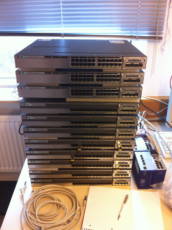
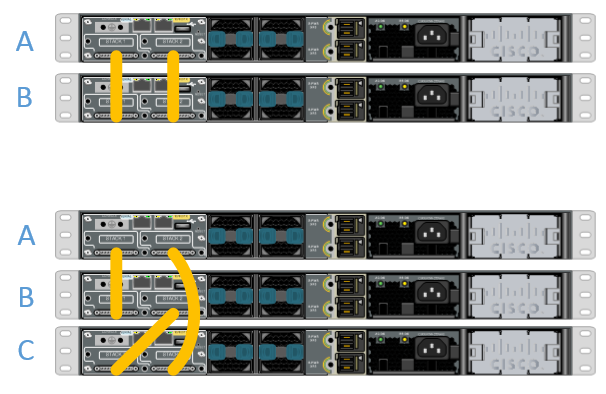
with Cisco StackWise you can bound several standalone-switches to one core-switch (the backbone will be connected together with Stacking-Cables (0,5, 1 or 3 meters):
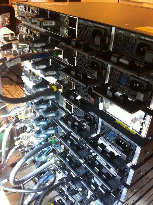
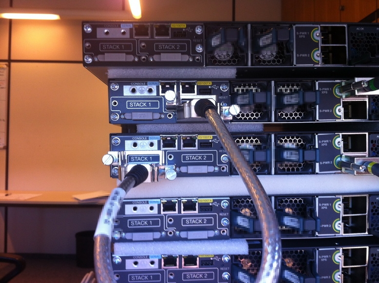
You can connect two devices with only one StackWise-Cable but for full bandwith and redundant connection, you need to connect the devices to a ring topology:
Before connecting two devices together, make sure that both devices have the same IOS software installed. The configuration of the StackWise Cluster is done automatically by connecting the stack cable. One switch will be the master within the cluster. The election is done as follow at connect or boot:
- Specified by user
- Switch with the highest IOS feature-set (Advanced Enterprise wins against Advanced IP Services)
- Uptime (longest running Switch wins)
- MAC Address (Switch with the lowest mac addresses will become master)
I recommend to configure the priority value of each switch so the configuration and the physical structure (top-down, A, B, C, etc.) keeps straight and didn’t confuse the administrator or someone who needs to troubleshoot the infrastructure OR you have differnet switch-models within one cluster. In our example Switch A is running for an hour and we connect another device (same device-model, same IOS software) to the main switch with a stacking cable. The second device “Switch B” will be select as Slave, because we didn’t configure anything and “Switch A” has a longer uptime. You will see that other interfaces are coming up and you can view all devices with this:
CoreSwitch# show switch
                                               Current
Switch#  Role      Mac Address     Priority     State
--------------------------------------------------------
 1       Master    0016.4748.ff12     5         Ready
 2       Slave     0016.9d59.db00     1         Ready
The stack member number is the same as can be seen in the interfaces:
interface GigabitEthernet1/0/1 = 1st Port of Switch with ID #1
interface GigabitEthernet2/0/1 = 1st Port of Switch with ID #2
You can define the priority of each switch. The higher the priority, the lower the switch stack-member-number. For example, we have three switches named 1,2 and 3 from top to down, 1 is connected with 2, 2 is connected with 3 and 3 is connected with 1 to connect a ring topology. We will configure the priority value with this commands:
switch 1 priority 15
switch 2 priority 14
switch 3 priority 13
in this case switch 2 will keep his stack-member-number 2, regardless at which time the device is rebooting or powered on. This is important because the configuration is shared on all switches within the StackWise Cluster and we don’t want to have similar port configurations on switch-members where the specific devices aren’t connected. Let us see this example:
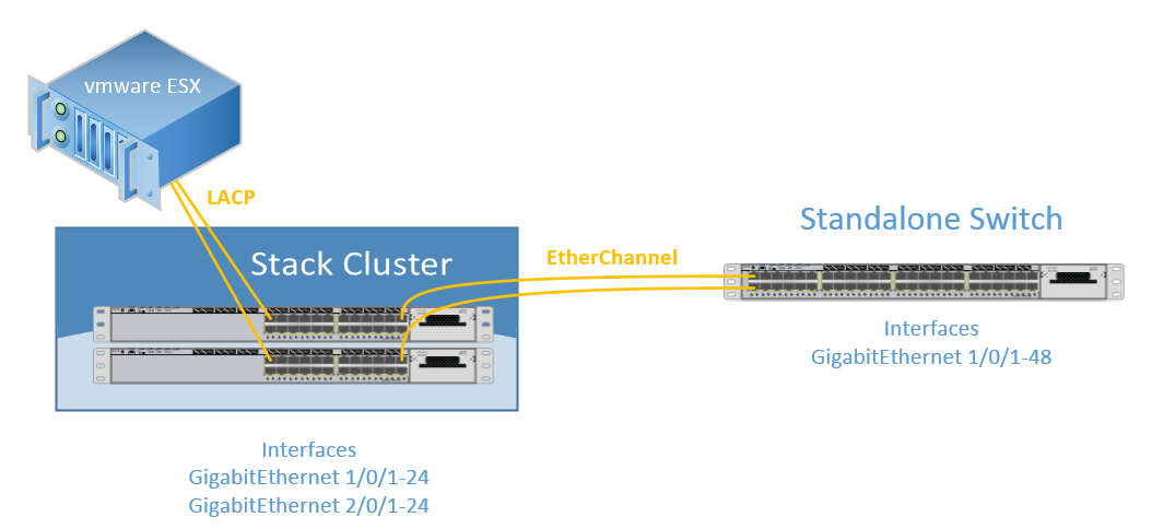
As you can see we are using two StackWise switches with the same model. The upper switch has ethernet ports defined from 1/0/1 to 1/0/24. The bottom switch has the ports 2/0/1 to 2/0/24. So the stack number defines the first backbone-number in the gigabitEthernet port name. When you didn’t configure the priorit values, the master election will always select the switch with the longest uptime as the master. Let us consider, that the first switch is a master and the second one (top-down) is the slave, if both switches are powered down and you first start the bottom one and after seconds the top one: The bottom switch will become the master node (port-configuration 1/../..) and the top one will be elected to a slave node with ID #2 (port-configuration 2/../..). When both switches are configured as a mirror, you will have no problem, but if the ports are configured different, you will get problems.
You can also stack different models together or can pre-configure a cluster configuration by just adding this line to your configuration:
switch 2 provision ws-c3750x-12s
In this case, the IOS knows that there will be another switch clustered together and the C3750X-12S has twelve ports, so you can see that another twelve ports are coming up to be configured. At the moment you connect a fresh 3750-X-12S Catalyst switch, the device will add himself to the Stack, reboots and the pre-configured ports can be used directly.
To view and verify you stack-healthness you can use this command:
CoreSwitch# show platform stack-manager all
I hope I could explain as much as you need feel free to add comments and help me to complete this guide and explainations. I will add a new post for switch virtualization built with HP A5500 switches soon.
source: https://networkguy.de/stackwise-configuration-with-cisco-catalyst-3750-x-series/
3)
I figured the glitch,
as ridiculous as it sounds, you need to carry the same config on both members of the port channel.
so whatever you put on your port channel you need to copy it to each indidvi.. member.
The same is not true when you are trying to make a VSL, you don't need to copy the same config from the port channel(VSL channel), to members.
Discover and save your favorite ideas. Come back to expert answers, step-by-step guides, recent topics, and more.
New here? Get started with these tips. How to use Community New member guide
