- Cisco Community
- Technology and Support
- Networking
- Switching
- VSS with Cisco 6509
- Subscribe to RSS Feed
- Mark Topic as New
- Mark Topic as Read
- Float this Topic for Current User
- Bookmark
- Subscribe
- Mute
- Printer Friendly Page
VSS with Cisco 6509
- Mark as New
- Bookmark
- Subscribe
- Mute
- Subscribe to RSS Feed
- Permalink
- Report Inappropriate Content
03-27-2017 04:40 AM - edited 03-08-2019 09:55 AM
Hi,
I have 4 nos of 6509 switch.
I want to configure VSS between two switches with virtual domain 10, and other two with the virtual domain 20.
Now my question is, can I configure HSRP between this two different VSS ?
Thanks
Debabrata Das
- Labels:
-
Other Switching
")
")
- Mark as New
- Bookmark
- Subscribe
- Mute
- Subscribe to RSS Feed
- Permalink
- Report Inappropriate Content
03-27-2017 05:09 AM
Hi
Yes its possible but its not a standard design , VSS was created to overcome the limitations of HSRP , would you not think of GLBP instead , your going to have a whole VSS setup in standby mode , that's an expensive setup of kit to be doing nothing just waiting to take over , I would try and use a design that at least keeps both units logically active , I haven't tested this VSS side by side but it should work in theory as 1 unit , we use VSS just as the core standalone there pretty resilient anyway setup without using 2 VSS design together
- Mark as New
- Bookmark
- Subscribe
- Mute
- Subscribe to RSS Feed
- Permalink
- Report Inappropriate Content
03-27-2017 05:33 AM
Okay.
Then what will be the best solution/design ?
I have already 4 nos. of 6509E.
Please suggest..
Thanks
Debabrata
- Mark as New
- Bookmark
- Subscribe
- Mute
- Subscribe to RSS Feed
- Permalink
- Report Inappropriate Content
03-27-2017 05:45 AM
whats your design setup currently are you core /dist/access or collapsed core
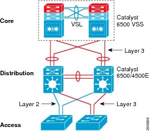
If its collapsed you could integrate a distribution layer , vss at the core , 2 6500s as the dist then your access layer hanging off the distribution switches , servers connected to the dist switches , pc/phones edge devices etc connected to the access
- Mark as New
- Bookmark
- Subscribe
- Mute
- Subscribe to RSS Feed
- Permalink
- Report Inappropriate Content
03-27-2017 05:55 AM
Okay..
Then what configuration is requited for distribution area ? Ether channel ?
Thanks
Debabrata
- Mark as New
- Bookmark
- Subscribe
- Mute
- Subscribe to RSS Feed
- Permalink
- Report Inappropriate Content
03-27-2017 06:04 AM
They should have specked the network before buying something so expensive if not required , sounds like someone with lot spare cash or tax payer money :)
Yes ether channel split to each VSS switch for full resiliency from the dist switches , that's the way we have our VSS setup bundled over the 2 units
32 Po32(SU) LACP Gi1/7/45(P) Gi2/7/45(P)
- Mark as New
- Bookmark
- Subscribe
- Mute
- Subscribe to RSS Feed
- Permalink
- Report Inappropriate Content
03-27-2017 06:55 AM
Hi,
Three ring network also is there..
1. Starting from 1st 6509E end 2nd 6509E - North Ring
2. Starting from 3rd 6509E end 4th 6509E- South Ring
2. Starting from 3rd 6509E end 4th 6509E- East Ring
1st and 2nd 6509E is installed in Server Room (Core Area)
3rd and 4th 6509E is installed in Main Control Room.
Thanks
Debabrata
- Mark as New
- Bookmark
- Subscribe
- Mute
- Subscribe to RSS Feed
- Permalink
- Report Inappropriate Content
03-27-2017 05:54 AM
Do you even need the additional two 6509 chassis?
I mean, do you have line cards which don't fit in the other two or is there any reason to actually use them (they do use a lot of power)?
If not, sell them or use them as a distribution layer, also with activated VSS (to overcome spanning-tree limitations).
- Mark as New
- Bookmark
- Subscribe
- Mute
- Subscribe to RSS Feed
- Permalink
- Report Inappropriate Content
03-27-2017 05:57 AM
Hi,
Customer already purchased 4 nos. of 6509E.
Thanks
Debabrata
- Mark as New
- Bookmark
- Subscribe
- Mute
- Subscribe to RSS Feed
- Permalink
- Report Inappropriate Content
03-27-2017 06:00 AM
Still no reason to use them... also why buy such expensive devices without first having requirements....
Anyway, in that case go for Marks suggestion, or for this:
http://www.cisco.com/c/en/us/products/collateral/switches/catalyst-6500-virtual-switching-system-1440/prod_qas0900aecd806ed74b.html
See figure 2 for how to connect a VSS distribution to a VSS core.
- Mark as New
- Bookmark
- Subscribe
- Mute
- Subscribe to RSS Feed
- Permalink
- Report Inappropriate Content
03-27-2017 06:50 AM
Okay ..
If I configure 2 switch as VSS core and rest 2 as VSS distribution..
what is the connectivity diagram ?
and please mentioned if any additional configure is require?
Thanks
Debabrata
- Mark as New
- Bookmark
- Subscribe
- Mute
- Subscribe to RSS Feed
- Permalink
- Report Inappropriate Content
03-27-2017 06:54 AM
You configure each pair as a VSS pair. Once this is done, you create an Etherchannel with 1-2 ports on each 6509 on each VSS pair. That's it.
Like it is shown here in figure 2: http://www.cisco.com/c/en/us/products/collateral/switches/catalyst-6500-virtual-switching-system-1440/prod_qas0900aecd806ed74b.html
Depending on your performance requirements you take 1 or 2 ports per 6509. You don't need to connect VSS-group1 with VSS-group2 over cross, because the VSS link between each VSS-group will transmit the traffic if one of the 4 6509 goes down.
- Mark as New
- Bookmark
- Subscribe
- Mute
- Subscribe to RSS Feed
- Permalink
- Report Inappropriate Content
03-27-2017 07:04 AM
Okay
for example i have switch A,B,C and D..
A and B is in VSS-group1 (port 1-2 communicate with each switch)
C and D is in VSS-group2 (port 1-2 communicate with each switch)
then what configuration is required for communication between A and C or D, vice versa .
Thanks
Debabrata
- Mark as New
- Bookmark
- Subscribe
- Mute
- Subscribe to RSS Feed
- Permalink
- Report Inappropriate Content
03-27-2017 07:21 AM
For VSS links (VSL) you need 4 times 10 Gbps ports (at least in the past you needed 40 gigs between Switch A and B).
Once the two separate VSS groups work you connect them together like this:
A <--> C - 2 cables (say Port 7 + 8 on A and on C)
B <--> D - 2 cables (say Port 7 + 8 on B and on D)
Port A7 + A8 + B7 + B8 into the same Etherchannel
Port B7 + B8 + D7 + D8 into the same Etherchannel
Done.
You could also cross one of the cables, but that is only required if you want to increase the redundancy for cases of special power outages, but it shouldn't be needed.
- Mark as New
- Bookmark
- Subscribe
- Mute
- Subscribe to RSS Feed
- Permalink
- Report Inappropriate Content
03-27-2017 07:30 AM
Okay ..
Then i need 8 nos of 10G
A-B 2 10G
A-C 2 10G
-----------------
C-D 2 10G
B-D 2 10G
and VSS configuration require only for between A-B and C-D... rest of the connections are normal ether channel... Am i right ?
Thanks
Debabrata
Discover and save your favorite ideas. Come back to expert answers, step-by-step guides, recent topics, and more.
New here? Get started with these tips. How to use Community New member guide