- Cisco Community
- Technology and Support
- Networking
- Routing
- Hi Willow,
- Subscribe to RSS Feed
- Mark Topic as New
- Mark Topic as Read
- Float this Topic for Current User
- Bookmark
- Subscribe
- Mute
- Printer Friendly Page
- Mark as New
- Bookmark
- Subscribe
- Mute
- Subscribe to RSS Feed
- Permalink
- Report Inappropriate Content
01-22-2016 03:02 AM - edited 03-05-2019 03:10 AM
Hello everyone,
been searching all over these forums and also read some text-books, but still I can`t find a good, decent and simple explanation about the cost changes in the peering neighbor over frame relay. I know how to do it , I know why you do it - but I can not understand the mechanics behind.
say you got a hub with an ethernet segment behind. this hub is connected to two spokes over frame relay. one spoke is a fast-speed cable (say 1 gig) and the other is much slower.
when those spoke routers advertise their route to that ethernet segment, they will both show the same cost. if I`d like to change that and make only the faster spoke an active route over the slower one, I could modify a p2m-non-broadcast neighbor statement with a lower cost value thus enabling only that route.
can anyone please give me a simple explanation as to why it should be done, who are the spokes advertising that ethernet segment to (it can`t be the hub - since he is the one who advertised the network in the first place) and why can`t I change the cost from the spokes rather than from the hub itself? I already need to configure them - so can`t I just take care of the of the cost then?
thanks ahead
willow
Solved! Go to Solution.
- Labels:
-
Routing Protocols
Accepted Solutions
")
- Mark as New
- Bookmark
- Subscribe
- Mute
- Subscribe to RSS Feed
- Permalink
- Report Inappropriate Content
01-22-2016 05:40 AM
Hi Willow,
I hope that by now, you're not nauseated by me jumping into your threads again and again...
I have to admit that I had troubles understanding your scenario. Let me just show you an example.

Assume that you have a hub and a dual-homed remote site that has two spoke routers for redundancy. One of them has a faster Serial interface, running at 1Mbps, the other spoke router uses only a slow 128Kbps serial interface. The hub itself uses a fast 1Mbps interface.
To understand the logic in the following paragraph, keep in mind that when OSPF computes the total cost of a path, it adds together the costs of the outgoing interfaces toward the destination. For example, from hub to the remote office LAN through S1, the total cost would be
Cost of Hub's interface toward S1 + Cost of S1's interface to the LAN
With the basic OSPF cost formula (Interface cost = 100Mbps / interface bandwidth), this cost would be 100/1 + 100/100 = 100 + 1 = 101, assuming the LAN runs at 100Mbps.
Obviously, if you let OSPF run in this network in basic PtMP or PtMP-NB mode without modifying costs manually, the hub will treat both S1 and S2 to be equally away, deriving the cost toward S1 and S2 from its serial interface bandwidth. Notice that S2's own serial interface cost of 100Mbps/128k = 781 does not matter to the Hub, because that interface is not an outgoing interface on the path toward the LAN.
The proper way of telling the Hub that S1 is, in terms of metrics, "closer" than S2, is by defining per-neighbor costs on the Hub (remember, the outgoing direction matters). So if you define your neighbors as
neighbor S1 cost 100
neighbor S2 cost 781
then you're telling the Hub that even though these two neighbors can be reached over the same interface on the Hub, they're not alike in their connectivity.
Would this help? Please feel welcome to ask further!
Best regards,
Peter
- Mark as New
- Bookmark
- Subscribe
- Mute
- Subscribe to RSS Feed
- Permalink
- Report Inappropriate Content
01-22-2016 07:50 AM
Hi Willow,
Thank you for your incredibly kind words!
The problem with your four loopbacks is that you have a problem in your addressing. All four loopbacks are in the same IP network 172.16.101.0/24, and so when you forced OSPF to stop advertising /32 addresses and have the true network advertised instead, this is what happened:
Each one of your four routers advertises the 172.16.101.0/24. However, each one also has the same network directly connected. Because the administrative distance of the directly connected network is lower than the route learned over OSPF (0 < 110), the OSPF-learned route does not even get added to the routing table. And even if it did, it would not be of much help because it is not unique.
The trick with advertising the /32 addresses was that even with your four loopback addresses overlapping (which is still illegal). each router had its routing table roughly in the following form:
Neighbor's Loopback 172.16.101.x/32
Neighbor's Loopback 172.16.101.y/32
Neighbor's Loopback 172.16.101.z/32
My Loopback         172.16.101.0/24
Notice that thanks to the longer prefix, all neighbor loopbacks were placed first in the routing table, and your own directly connected network was placed afterwards. So the loopbacks were reachable thanks to the plain longest-prefix-match rule.
If you want to use ip ospf network point-to-point with your loopbacks, you must be sure to put them into unique IP networks (which they should be in, anyway), say: 172.16.101.1/24 for R1, 172.16.102.1/24 for R2, 172.16.103.1/24 for R3, and 172.16.104.1/24 for R4.
Best regards,
Peter
- Mark as New
- Bookmark
- Subscribe
- Mute
- Subscribe to RSS Feed
- Permalink
- Report Inappropriate Content
01-22-2016 05:40 AM
Hi Willow,
I hope that by now, you're not nauseated by me jumping into your threads again and again...
I have to admit that I had troubles understanding your scenario. Let me just show you an example.
Assume that you have a hub and a dual-homed remote site that has two spoke routers for redundancy. One of them has a faster Serial interface, running at 1Mbps, the other spoke router uses only a slow 128Kbps serial interface. The hub itself uses a fast 1Mbps interface.
To understand the logic in the following paragraph, keep in mind that when OSPF computes the total cost of a path, it adds together the costs of the outgoing interfaces toward the destination. For example, from hub to the remote office LAN through S1, the total cost would be
Cost of Hub's interface toward S1 + Cost of S1's interface to the LAN
With the basic OSPF cost formula (Interface cost = 100Mbps / interface bandwidth), this cost would be 100/1 + 100/100 = 100 + 1 = 101, assuming the LAN runs at 100Mbps.
Obviously, if you let OSPF run in this network in basic PtMP or PtMP-NB mode without modifying costs manually, the hub will treat both S1 and S2 to be equally away, deriving the cost toward S1 and S2 from its serial interface bandwidth. Notice that S2's own serial interface cost of 100Mbps/128k = 781 does not matter to the Hub, because that interface is not an outgoing interface on the path toward the LAN.
The proper way of telling the Hub that S1 is, in terms of metrics, "closer" than S2, is by defining per-neighbor costs on the Hub (remember, the outgoing direction matters). So if you define your neighbors as
neighbor S1 cost 100
neighbor S2 cost 781
then you're telling the Hub that even though these two neighbors can be reached over the same interface on the Hub, they're not alike in their connectivity.
Would this help? Please feel welcome to ask further!
Best regards,
Peter
- Mark as New
- Bookmark
- Subscribe
- Mute
- Subscribe to RSS Feed
- Permalink
- Report Inappropriate Content
01-22-2016 06:25 AM
Hi Peter,
nauseated? I feel privileged that someone with such an extensive knowledge as yourself can find the time to solve these issues. when I see an answer from you - I know the subject would be fully understood. actually, your topology is exactly what I had in mind, just didn`t describe it as clearly as you did... another subject understood! again, thanks alot for that :)
hope it won`t be too rude to ask another OSPF related question while wer`e at it...
OSPF advertises loopback interfaces as /32 by default. if you want to change that so it advertises the original subnet, you need to change the OSPF network type to p2p on the loopback interface. well, that`s what I did and now I can`t ping those interfaces, while the rest of the (broadcast) network is advertised correctly.
the layout is fairly simple: four routers connected to a switch as usual. this time I added the topology:

the configuration is simple as well: all routers advertise the network and the loopbacks in a 0.0.0.0 wildcard. here are the relevant parts of the running-config
#######
router 1
#######
interface Loopback0
ip address 172.16.101.1 255.255.255.0
ip ospf network point-to-point
!
interface FastEthernet0/0
ip address 10.1.1.1 255.255.255.0
duplex auto
speed auto
!
!
!
router ospf 1
router-id 1.1.1.1
log-adjacency-changes
network 172.16.101.1 0.0.0.0 area 0
network 10.1.1.1 0.0.0.0 area 0
######
router 2
######
interface Loopback0
ip address 172.16.101.2 255.255.255.0
ip ospf network point-to-point
!
interface FastEthernet0/0
ip address 10.1.1.2 255.255.255.0
duplex auto
speed auto
!
!
!
router ospf 1
router-id 2.2.2.2
log-adjacency-changes
network 172.16.101.2 0.0.0.0 area 0
network 10.1.1.2 0.0.0.0 area 0
######
router 3
######
interface Loopback0
ip address 172.16.101.3 255.255.255.0
ip ospf network point-to-point
!
interface FastEthernet0/0
ip address 10.1.1.3 255.255.255.0
duplex auto
speed auto
!
!
!
router ospf 1
router-id 3.3.3.3
log-adjacency-changes
network 172.16.101.3 0.0.0.0 area 0
network 10.1.1.3 0.0.0.0 area 0
########
router 4
########
interface Loopback0
ip address 172.16.101.4 255.255.255.0
ip ospf network point-to-point
!
interface FastEthernet0/0
ip address 10.1.1.4 255.255.255.0
duplex auto
speed auto
!
!
!
router ospf 1
router-id 4.4.4.4
log-adjacency-changes
network 172.16.101.4 0.0.0.0 area 0
network 10.1.1.4 0.0.0.0 area 0
####################
where did I go wrong? as you can see, nothing here is configured carelessly... can you point me out?
thanks again,
willow
- Mark as New
- Bookmark
- Subscribe
- Mute
- Subscribe to RSS Feed
- Permalink
- Report Inappropriate Content
01-22-2016 07:50 AM
Hi Willow,
Thank you for your incredibly kind words!
The problem with your four loopbacks is that you have a problem in your addressing. All four loopbacks are in the same IP network 172.16.101.0/24, and so when you forced OSPF to stop advertising /32 addresses and have the true network advertised instead, this is what happened:
Each one of your four routers advertises the 172.16.101.0/24. However, each one also has the same network directly connected. Because the administrative distance of the directly connected network is lower than the route learned over OSPF (0 < 110), the OSPF-learned route does not even get added to the routing table. And even if it did, it would not be of much help because it is not unique.
The trick with advertising the /32 addresses was that even with your four loopback addresses overlapping (which is still illegal). each router had its routing table roughly in the following form:
Neighbor's Loopback 172.16.101.x/32
Neighbor's Loopback 172.16.101.y/32
Neighbor's Loopback 172.16.101.z/32
My Loopback         172.16.101.0/24
Notice that thanks to the longer prefix, all neighbor loopbacks were placed first in the routing table, and your own directly connected network was placed afterwards. So the loopbacks were reachable thanks to the plain longest-prefix-match rule.
If you want to use ip ospf network point-to-point with your loopbacks, you must be sure to put them into unique IP networks (which they should be in, anyway), say: 172.16.101.1/24 for R1, 172.16.102.1/24 for R2, 172.16.103.1/24 for R3, and 172.16.104.1/24 for R4.
Best regards,
Peter
- Mark as New
- Bookmark
- Subscribe
- Mute
- Subscribe to RSS Feed
- Permalink
- Report Inappropriate Content
01-22-2016 11:36 AM
Hi Peter,
So... why would you want to change the /32 from the beginning? what purpose does it serve?
just want to mention that in GNS3 my configuration works like a charm and in packet tracer it doesn`t. that comes together with the fact that in GNS3 you can do overlapped IP addressing and in pt you can not (as seen in this example). are you aware of this difference? since GNS3 is an emulator I assume that in real-life my configuration would work just fine. am I right?
thanks alot,
willow
- Mark as New
- Bookmark
- Subscribe
- Mute
- Subscribe to RSS Feed
- Permalink
- Report Inappropriate Content
01-22-2016 03:30 PM
Hi Willow,
So... why would you want to change the /32 from the beginning? what purpose does it serve?
Well, sometimes, you need to emulate a network that does not physically exist yet. You can either set it up as a secondary address on some interface (which may not be a particularly good idea), or you can create a Loopback interface and configure the network there. Obviously, when you need to advertise that network in a routing protocol, you want it to be advertised with its true netmask, not just the IP address with a /32 mask.
However, loopback or not, having multiple routers configured with the same directly connected network is legal only if these routers truly share a common link with thins network. This obviously cannot be accomplished with virtual loopback interfaces. Remember, when a router adverties a network, it claims direct connectivity to every IP in that network. In the way you have configured your loopbacks, this is not the case - even though each of your routers advertises the entire 172.16.101.0/24 network, it has a direct connectivity only to a single IP address out of this range. This is a violation of basic connectivity assumptions in IP.
just want to mention that in GNS3 my configuration works like a charm and in packet tracer it doesn`t.
To be honest, I do not see how your configuration with the loopbacks in the same IP network could work if you configured the ip ospf network point-to-point on them. Are you sure about this?
that comes together with the fact that in GNS3 you can do overlapped IP addressing and in pt you can not (as seen in this example). are you aware of this difference?
Willow, this does not make sense. The reason why it should not work is explained in my previous post. I may test it out in my Dynamips as well. Will need some time for this.
Best regards,
Peter
- Mark as New
- Bookmark
- Subscribe
- Mute
- Subscribe to RSS Feed
- Permalink
- Report Inappropriate Content
01-22-2016 04:21 PM
- Mark as New
- Bookmark
- Subscribe
- Mute
- Subscribe to RSS Feed
- Permalink
- Report Inappropriate Content
01-23-2016 02:06 AM
...and again, here you can see this guy who configures two multipoint sub-interfaces with the same subnet (/24), where one address is 172.16.1.1 and the other is 172.16.1.2 - on the same router. this action can not be done in PT becuase, as you explained, the addresses have to be unique and OSPF needs to assume connectivity to all of the network. but here this guy does it anyhow on GNS3
(from 22:00 to 23:15)
- Mark as New
- Bookmark
- Subscribe
- Mute
- Subscribe to RSS Feed
- Permalink
- Report Inappropriate Content
01-23-2016 03:10 AM
Hi Willow,
I had a brief look on the videos you have referenced.
In the first video (0002 OSPF Broadcast Mode), the loopbacks on R1 through R4 are in different networks - R1 is 172.16.101.1/24, R2 is 172.16.102.2/24, R3 is 172.16.103.3/24, R4 is 172.16.104.4/24. Here, the author is doing exactly what he should be doing - if using loopbacks, have each of them in a unique network.
The second video shows a different issue, not related to loopbacks on different devices being incorrectly placed into the same IP network. In the second video, the author is, apparently without knowing it himself, using a little-known feature of serial interfaces that indeed allow multiple interfaces to be in the same network. Personally, I have never found out a definitive explanation of why Cisco devices allow this exemption on serial interfaces (I have a feeling that it is simply an alternative way of accomplishing the functionality of ip unnumbered links). In any case, I do not think that in the second video, this feature has been used appropriately. There is no reason to define multiple (sub)interfaces and have them in the same IP subnet.
I am not sure if I haven't raised your confusion instead of dispelling it - please, as always, feel welcome to ask further.
Best regards,
Peter
- Mark as New
- Bookmark
- Subscribe
- Mute
- Subscribe to RSS Feed
- Permalink
- Report Inappropriate Content
01-23-2016 03:41 AM
Hi Peter,
My bad. truly, the loopback interfaces are on DIFFERENT networks, and not as I thought they were. that was the source of my confusion...
as so, I thought the second video demonstration is related, since if you could assign the same network to the same router on different sub-interfaces - why can`t you do that on a loopback interface? but, as you said, it is a feature on real devices for accomplishing the functionality of IP unnumbered links, a subject I know nothing about (yet!)
as always, I would like to thank you deeply for pointing out and clarifying issues with great patience and tremendous knowledge. thanks alot!
willow
- Mark as New
- Bookmark
- Subscribe
- Mute
- Subscribe to RSS Feed
- Permalink
- Report Inappropriate Content
01-23-2016 04:02 AM
Hi Willow,
I thought the second video demonstration is related, since if you could assign the same network to the same router on different sub-interfaces - why can`t you do that on a loopback interface?
Try not to confuse two different things: Loopbacks on different routers placed into the same network versus different subinterfaces on the same router placed into the same network. Our problem wasn't having multiple loopbacks on the same router in the same network - our problem was having multiple loopbacks on different routers in the same network.
The problem created with multiple loopbacks on different routers in the same network is basically the same problem you would have if you used a public IP space in your home network. If your home PCs tried to access the real severs in the overlapping IP space out in the internet, their packets would never reach the internet because by basic IP routing rules, the packets are already at their destination network even though they have never left your home network.
In addition, imagine a fifth router connected to the same switch in the network with the former four routers having their loopbacks in the same network. This fifth router does not have any loopback, it just learns about other networks via OSPF. Now, this fifth router would learn about the network 172.16.101.0/24 from four different routers, R1 through R4, with the same cost. It would think that these are equal cost paths to the same destination and that all those routers have direct access to all hosts in the 172.16.101.0/24 network. So the fifth router would doing load-balancing, and guess what: Statistically, only 1/4 of all traffic would go the correct way. Imagine that the fifth router tried to ping 172.16.101.1 and decided to send the packets to R2. R2 would receive them but on the 172.16.101.0/24 network, it has only its own address 172.16.101.2 and it knows that there are no more hosts because the interface with this network is a loopback interface - so R2 would drop the packet right away.
I hope this helps.
Best regards,
Peter
- Mark as New
- Bookmark
- Subscribe
- Mute
- Subscribe to RSS Feed
- Permalink
- Report Inappropriate Content
01-23-2016 05:18 AM
Hi Peter,
You should write a book. thank you so much!!
willow
- Mark as New
- Bookmark
- Subscribe
- Mute
- Subscribe to RSS Feed
- Permalink
- Report Inappropriate Content
01-23-2016 05:29 AM
Hi Willow,
You should write a book.
LOL :) Thank you - I did :)
http://www.ciscopress.com/store/ccie-routing-and-switching-v5.0-official-cert-guide-9781587143960
Best regards,
Peter
- Mark as New
- Bookmark
- Subscribe
- Mute
- Subscribe to RSS Feed
- Permalink
- Report Inappropriate Content
01-23-2016 06:27 AM
wow! that is impressive. but then again, I could have guessed it by reading your replays alone... :)
best regards,
willow
- Mark as New
- Bookmark
- Subscribe
- Mute
- Subscribe to RSS Feed
- Permalink
- Report Inappropriate Content
01-25-2016 02:33 AM
Hi Peter,
I hope you don`t mind me bothering you again on the subject... can you please take a quick look at my question?
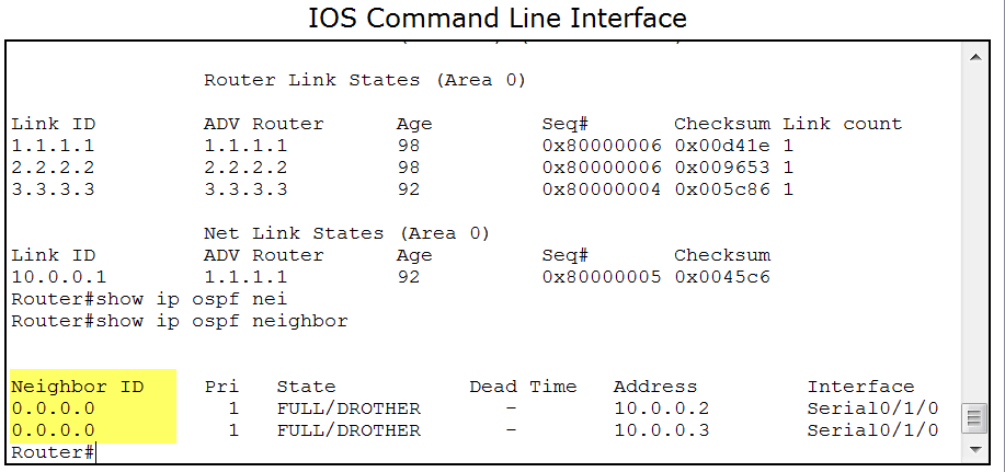
I configured a full mesh all-in-the-same-IP network all-on-physical-interfaces all-using-map-ip statements, resulting in NBMA. now when configuring OSPF it just doesn`t work, no matter what I do. I mean - it comes up, and it shows in the interface and in the ospf data - but when trying to see the neighbors they show as 0.0.0.0 (with RID configured!) and sometimes on exstart, sometimes on INIT, sometimes on FULL and even if I cancel DR selection (priority=0) they keep showing up as drother. debug also show them trying to send DBD in a 2way-state.
help, I tried everything. broadcast, no-broadcast, physical, sub interface, clearing process, restating routers... the only thing I didn`t do yet is throw the whole pc outside my window. nothing seems to work, it always bounces back to neighbors on 0.0.0.0 even though the all got a RID.
another thing I wanted to ask you: I configured a network NBMA on one side and p2p on the other, and it worked very well without configuring any timers. how come? when you say "you need to sync the timers between different ospf networks" - don`t you mean exactly those situations, when I got two different networks on the same topology? do how come it wroks without doing that?
thank you very much for helping out, yet again
willow

Discover and save your favorite ideas. Come back to expert answers, step-by-step guides, recent topics, and more.
New here? Get started with these tips. How to use Community New member guide
