- Cisco Community
- Technology and Support
- Networking
- Switching
- Ask the Expert: Implementing and Troubleshooting Virtual Switching System (VSS) on Cisco Catalyst Sw...
- Subscribe to RSS Feed
- Mark Topic as New
- Mark Topic as Read
- Float this Topic for Current User
- Bookmark
- Subscribe
- Mute
- Printer Friendly Page
Ask the Expert: Implementing and Troubleshooting Virtual Switching System (VSS) on Cisco Catalyst Switches 4500 and 6500
- Mark as New
- Bookmark
- Subscribe
- Mute
- Subscribe to RSS Feed
- Permalink
- Report Inappropriate Content
09-04-2015 03:17 PM - edited 03-08-2019 01:39 AM
![]() Virtual Switching System (VSS) is network system virtualization technology that pools multiple Cisco Catalyst 6500 Series Switches into one virtual switch, increasing operational efficiency, boosting nonstop communications, and scaling system bandwidth capacity to 1.4 Tbps. At the initial phase, a VSS will allow two physical Cisco Catalyst 6500 Series Switches to operate as a single logical virtual switch called a virtual switching system 144.
Virtual Switching System (VSS) is network system virtualization technology that pools multiple Cisco Catalyst 6500 Series Switches into one virtual switch, increasing operational efficiency, boosting nonstop communications, and scaling system bandwidth capacity to 1.4 Tbps. At the initial phase, a VSS will allow two physical Cisco Catalyst 6500 Series Switches to operate as a single logical virtual switch called a virtual switching system 144.
his session will provide an opportunity to learn and ask questions about how to implement, configure and troubleshoot VSS in Cisco Catalyst Switches 6500 and 4500.
Ask questions from Monday, September 7 to Friday, September 18, 2015
Featured Experts
 InayathUlla Sharieff is a Customer support engineer in High-Touch Technical Services (HTTS) team supporting LAN Switching and Data center Products. His areas of expertise include Cisco Catalyst 2000,3000,4000 ,6500 and Cisco Nexus 7000 Switches. Shariff has over 8 years of industry experience working with large enterprise and Service Provider networks. He holds Bachelors in Computer Sciences degree and these Cisco certifications: CCNA, CCNP (in Routing and Swtiching), and CCIE in R&S (# 43263). He is pursuing the CCIE in Data Centers.
 Suresh Vs is a Customer Support Engineer in High-Touch Technical Services (HTTS) at Cisco Bangalore, India. He has over 11 years of industry experience working with large Enterprise and Service Provider networks. He has been working with HTTS from past 4 years and supporting LAN Switching and Data center Products. His areas of expertise include Cisco Catalyst 2000, 3000, 4000, 6500 and Cisco Nexus 7000 Switches. Suresh holds a Bachelor's of Sciences in Electrical and Electronics Engineering from Madras University. He has these certifications: CCNA, CCNP, CCIE Data Center (# 46658).
Find other https://supportforums.cisco.com/expert-corner/events.
** Ratings Encourage Participation! **
Please be sure to rate the Answers to Questions
- Labels:
-
Other Switching
")
- Mark as New
- Bookmark
- Subscribe
- Mute
- Subscribe to RSS Feed
- Permalink
- Report Inappropriate Content
09-17-2015 11:56 PM
Hi Support Sbt,
I got your question now. The reason it is showing as yes because you have configured it on the switch virtual domain( or it is on/enabled by default).
If you want to see as "NO" then do this:-
switch virtual domain 1
no dual-active detection fast-hello
no dual-active detection pagp
(config-vs-domain)#do sh switch virtual dual-ac su
Pagp dual-active detection enabled: No>>>>>>>. Now you can see it as no.
Fast-hello dual-active detection enabled: No>>>>>>. Now you can see it as no.
HTH
regards
inayath
****Please do not forget to rate the post if helpfull********
- Mark as New
- Bookmark
- Subscribe
- Mute
- Subscribe to RSS Feed
- Permalink
- Report Inappropriate Content
09-18-2015 12:37 AM
Hi Inayath,
i could not see anything explicitly configured as you said . Below is the root domain configuration part . As i understood even if we did not have dedicated link for fast-hello , it would be fine .please correct me i am wrong . By the way switch is 6807
switch virtual domain 2
switch mode virtual
switch 1 priority 110
Thanks
- Mark as New
- Bookmark
- Subscribe
- Mute
- Subscribe to RSS Feed
- Permalink
- Report Inappropriate Content
09-18-2015 01:50 AM
Yes it looks to be by default hence most of the default configuration will not be shown under the config.
Try to configure the suggested cmd to disable that or to see "NO" option in front of that.
If you want to see as "NO" then do this:-
switch virtual domain 1
no dual-active detection fast-hello
no dual-active detection pagp
(config-vs-domain)#do sh switch virtual dual-ac su
Pagp dual-active detection enabled: No>>>>>>>. Now you can see it as no.
Fast-hello dual-active detection enabled: No>>>>>>. Now you can see it as no.
HTH
regards
inayath
****Please do not forget to rate the post if helpfull********
- Mark as New
- Bookmark
- Subscribe
- Mute
- Subscribe to RSS Feed
- Permalink
- Report Inappropriate Content
09-18-2015 03:27 AM
Hi Inayath
Finally , Do we need to assign a dedicated link for fast -hello, if not what are the problems may happen
Thanks
- Mark as New
- Bookmark
- Subscribe
- Mute
- Subscribe to RSS Feed
- Permalink
- Report Inappropriate Content
09-18-2015 09:52 AM
Hi,
Yes you need a dedicated link to carry the fast-hello messages.
Once you configure fast hello dual-active mode will will automatically remove all existing configuration from the interface.
If you dont configure it then you will have problem when the vsl link goes down .
More info:-
dual-active fast-hello - Uses special hello messages over a backup Ethernet connection. You can configure both detection methods to be active at the same time.
For line redundancy, Cisco recommends dedicating at least two ports per switch for dual-active detection.
For module redundancy, the two ports can be on different switching modules in each chassis, and should be on different modules than the VSL links, if feasible.
To use the dual-active fast hello packet detection method, you must provision a direct Ethernet connection between the two VSS chassis. You can dedicate up to four non-VSL links for this purpose When you configure fast hello dual-active interface pairs, note the following information:
- You can configure a maximum of four interfaces on each chassis to connect with the other chassis in dual-active interface pairs.
- Each interface must be directly connected to the other chassis and must not be a VSL link. We recommend using links from a switching module not used by the VSL.
- Each interface must be a physical port. Logical ports such as an SVI are not supported.
- Configuring fast hello dual-active mode will automatically remove all existing configuration from the interface and will restrict the interface to fast hello dual-active configuration commands.
- Unidirectional link detection (UDLD) will be disabled on fast hello dual-active interface pairs.
Refer:
Use of Management port
A hung Route Processor (RP) could lock up the console, leaving it impossible to recover or determine the state
of the switch with no way to login to it.
A solution in such critical situations is to have a `backdoor' access into the switch to help restore it. This is addressed on next-generation supervisor engines through a new processor called the Connectivity Management Processor (CMP), which exists in conjunction with the primary Route Processor (RP).
The CMP on the Supervisor Engine 2T supports a front panel 10/100/1000 management port.
Refer:
http://www.cisco.com/en/US/prod/collateral/switches/ps5718/ps708/white_paper_c11-663635.html
HTH
REgards
inayath
*********Please do not forget to rate all usefull posts*********
- Mark as New
- Bookmark
- Subscribe
- Mute
- Subscribe to RSS Feed
- Permalink
- Report Inappropriate Content
09-16-2015 05:51 AM
Hello Iniyath | Suresh,
For the dual-active recovery, can the switch recover itself and UP as standby without manual intervention?
Warm Regards,
Thiyagarajan B
- Mark as New
- Bookmark
- Subscribe
- Mute
- Subscribe to RSS Feed
- Permalink
- Report Inappropriate Content
09-16-2015 07:28 AM
Thiyagarajan,
Yes if you have confiugred the dual active recovery once the VSL link is resotred the switch will recover itself and UP as standby.
Please find complete explanation below which will help you to understand in details:-
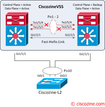
VSL failure
The failure of a single VSL link is discovered by the active supervisor engine, either through a link-down event or through the failure of periodic VSLP messages sent across the link to check the VSL link state. Availability is not affected for those data flows that do not use the VSL.

The active supervisor engine discovers the failure of the “entire” VSL either through a link-down event or through the failure of the periodic VSLP messages sent across the member links to check the VSL link status. From the perspective of the active virtual switch chassis, the standby virtual switch is lost. The standby virtual switch chassis also views the active virtual switch chassis as failed and transitions to active virtual switch state through an SSO switchover. This scenario is known as a dual-active scenario and the duplication of this configuration can possibly have adverse effects to the network topology and traffic.
To avoid this disruptive scenario, you should configure one of these methods:
- Enhanced PAgP
- Layer 3 BFD
- Fast Hello
In this case the Fast hello link method is implemented.
Upon detecting the dual-active condition, the original active chassis enters intorecovery mode and brings down all of its interfaces except the VSL and nominated management interfaces. This effectively removes the device from the network.
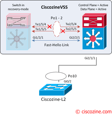
You will see the following messages on the active virtual switch to indicate that a dual-active scenario has occurred:
CiscozineVSS#
Jan 23 11:57:37.647: %VSLP-SW1_SP-3-VSLP_LMP_FAIL_REASON: Te1/5/5: Link down
Jan 23 11:57:37.647: %VSLP-SW1_SP-2-VSL_DOWN: Last VSL interface Te1/5/5 went down
Jan 23 11:57:37.735: %VSLP-SW1_SP-2-VSL_DOWN: All VSL links went down while switch is in ACTIVE role
Jan 23 11:57:37.799: %LINEPROTO-SW1_SP-5-UPDOWN: Line protocol on Interface TenGigabitEthernet1/5/5, changed state to down
Jan 23 11:57:37.803: %LINEPROTO-SW1_SP-5-UPDOWN: Line protocol on Interface Port-channel1, changed state to down
Jan 23 11:57:37.803: %LINK-SW1_SP-3-UPDOWN: Interface Port-channel1, changed state to down
Jan 23 11:57:37.807: %LINK-SW1_SP-3-UPDOWN: Interface TenGigabitEthernet1/5/5, changed state to down
Jan 23 11:57:37.875: %DUAL_ACTIVE-SW1_SP-1-DETECTION: Fast-hello running on Gi1/2/1 detected dual-active condition
Jan 23 11:57:37.875: %DUAL_ACTIVE-SW1_SP-1-RECOVERY: Dual-active condition detected: Starting recovery-mode, all non-VSL and non-excluded interfaces have been shut down
CiscozineVSS(recovery-mode)#
The following messages on the standby virtual switch console indicate that a dual-active scenario has occurred:
CiscozineVSS-sdby#
Jan 23 11:57:37.647: %VSLP-SW2_SPSTBY-3-VSLP_LMP_FAIL_REASON: Te2/5/5: Link down
Jan 23 11:57:37.647: %VSLP-SW2_SPSTBY-2-VSL_DOWN:   Last VSL interface Te2/5/5 went down
Jan 23 11:57:37.651: %VSLP-SW2_SPSTBY-2-VSL_DOWN:   All VSL links went down while switch is in Standby role
Jan 23 11:57:37.651: %DUAL_ACTIVE-SW2_SPSTBY-1-VSL_DOWN: VSL is down - switchover, or possible dual-active situation has occurred
Jan 23 11:57:37.651: %PFREDUN-SW2_SPSTBY-6-ACTIVE: Initializing as Virtual Switch ACTIVE processor
Jan 23 11:57:39.559: %LINK-3-UPDOWN: Interface TenGigabitEthernet2/5/5, changed state to down
Jan 23 11:57:39.559: %LINEPROTO-SW2_SP-5-UPDOWN: Line protocol on Interface TenGigabitEthernet2/5/5, changed state to down
Jan 23 11:57:40.579: %OIR-SW2_SP-6-INSREM: Switch 1 Physical Slot 1 - Module Type LINE_CARD  removed
Jan 23 11:57:40.899: %OIR-SW2_SP-6-INSREM: Switch 1 Physical Slot 2 - Module Type LINE_CARD  removed
Jan 23 11:57:40.991: %OIR-SW2_SP-6-INSREM: Switch 1 Physical Slot 3 - Module Type LINE_CARD  removed
Jan 23 11:57:41.107: %OIR-SW2_SP-6-INSREM: Switch 1 Physical Slot 5 - Module Type LINE_CARD  removed
Jan 23 11:58:00.335: %VSLP-SW2_SP-2-VSL_DOWN:   All VSL links went down while switch is in ACTIVE role
CiscozineVSS#
This is confirmed by the show command:
CiscozineVSS#show switch virtual redundancy
                  My Switch Id = 2
                Peer Switch Id = 1
        Last switchover reason = active unit removed
    Configured Redundancy Mode = sso
     Operating Redundancy Mode = sso

Switch 2 Slot 5 Processor Information :
-----------------------------------------------
        Current Software state = ACTIVE
       Uptime in current state = 0 minutes
                 Image Version = Cisco IOS Software, s72033_rp Software (s72033_rp-ADVENTERPRISEK9-M), Version 15.1(2)SY, RELEASE SOFTWARE (fc4)
Technical Support: http://www.cisco.com/techsupport
Copyright (c) 1986-2013 by Cisco Systems, Inc.
Compiled Wed 04-Sep-13 13:05 by prod_rel_team
                          BOOT = bootdisk:s72033-adventerprisek9-mz.151-2.SY.bin,12;
        Configuration register = 0x2102
                  Fabric State = ACTIVE
           Control Plane State = ACTIVE

Peer information is not available because
it is in 'DISABLED' state
CiscozineVSS#
When the VSL is restored, the following messages are displayed on the console and the switch in recovery mode (previous active virtual switch) reloads:
Jan 26 13:23:34.877: %DUALACTIVE-1-VSL_RECOVERED: VSL has recovered during dual-active situation: Reloading switch 1
Jan 26 13:23:34.909: %SYS-5-RELOAD: Reload requested Reload Reason: Reload Command.
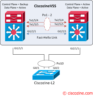
After the reloading, the VSS is recovered; the control plane remains active on the previous standby virtual switch. To force a switchover use the command:
redundancy force-switchover
HTH
Inayath
**************Please do not forget to rate the post is usefull**********
- Mark as New
- Bookmark
- Subscribe
- Mute
- Subscribe to RSS Feed
- Permalink
- Report Inappropriate Content
09-16-2015 10:42 PM
Hi ,
What are the parameters to be verified vss is healthy and best practice has been followed ?
Thanks
- Mark as New
- Bookmark
- Subscribe
- Mute
- Subscribe to RSS Feed
- Permalink
- Report Inappropriate Content
09-17-2015 12:07 AM
What are the parameters to be verified vss is healthy and best practice has been followed ?
Answer:-
1- Make sure your Hardware devices the configuration is good. Once that is good and expected move to do the health checkup.
Few thingss to check are:-
1- Interface & PO status(Check for errors/drops any)
2- CPU check to make sure we are not hitting any high cpu.
3- STP -- No loops.
4- show switch virtual -- to check the control plan health.
5- show switch virtual link:- to check LMP state and flags.
6- show vslp lmp counters -- again LMP check for the Rx error.
7- Show module switch all --> to check the module status on both the chasis.
8- show switch virtual redundancy mismatch.
9- show diagnostic resumt module all details. >> to check the diagnostic result.
Hope this helps.
Regards
Inayath
******please do not forget to rate if this info is helpfull***

- Mark as New
- Bookmark
- Subscribe
- Mute
- Subscribe to RSS Feed
- Permalink
- Report Inappropriate Content
11-23-2017 12:28 AM
Hi, I am having a problem configuring dual-active detection on the VSL link, after configuring the dual-active detection with the following commands:
int po30
shut

switch virtual domain 100
dual-active detection pagp
dual-active detection pagp trust channel-group 30

int po30
no shut
The VSL link stays down/down and the stanby switch enters in recovery-mode.
Can anyone help me with this problem??
- « Previous
- Next »
Discover and save your favorite ideas. Come back to expert answers, step-by-step guides, recent topics, and more.
New here? Get started with these tips. How to use Community New member guide