- Subscribe to RSS Feed
- Mark Topic as New
- Mark Topic as Read
- Float this Topic for Current User
- Bookmark
- Subscribe
- Mute
- Printer Friendly Page
- Mark as New
- Bookmark
- Subscribe
- Mute
- Subscribe to RSS Feed
- Permalink
- Report Inappropriate Content
03-23-2017 01:11 PM - edited 03-08-2019 09:53 AM
Good afternoon everyone,
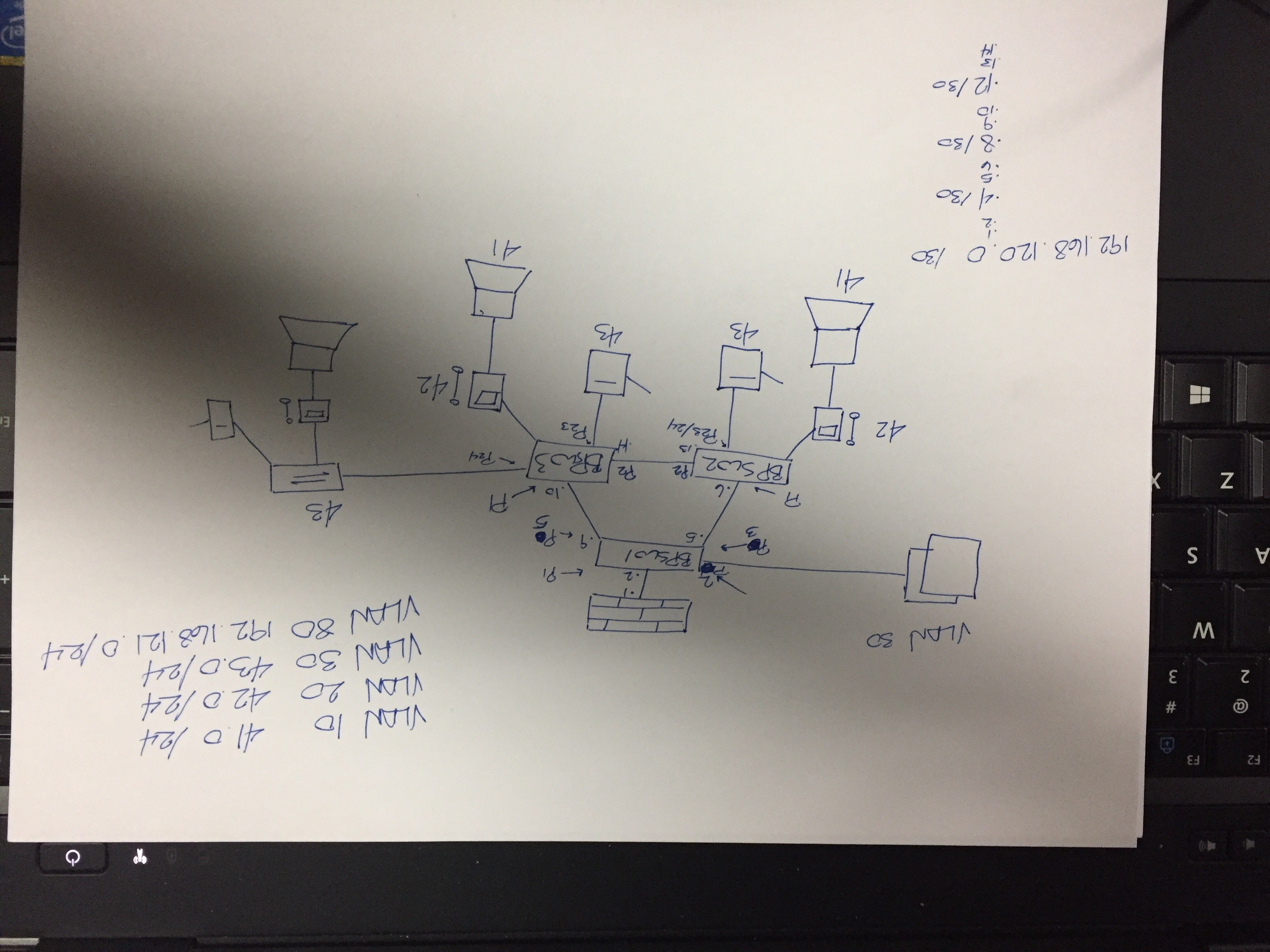
I'm configuring DHCP on a 3750 (BPSW1) and it works if I configure trunks or plug a VoIP phone in to a local port of BPSW1. However, I have a need for layer 3 switches to be tossed in named (BPSW2) and (BPSW3) for example.
On switch 2 I have configured the following:
!
interface Vlan10
ip address 172.16.41.1 255.255.255.0
ip helper-address 192.168.120.5
!
interface Vlan20
ip address 172.16.42.1 255.255.255.0
ip helper-address 192.168.120.5
!
192.168.120.5 is an interface on BPSW1 on which the DHCP server resides. I'm willing to bet that the IP helper is configured incorrectly. I know that it needs to be the IP address of BPSW1 but it doesn't have one other than the Vlan interfaces. I've attached a drawn diagram for review as well.
I suppose my questions are:
1) Is my IP-HELPER command misconfigured?
2) If so, what is the best practice for assigning an IP to a L3 switch for IP-HELPER purposes?
Thanks for the help everyone.
Solved! Go to Solution.
- Labels:
-
Other Switching
Accepted Solutions
- Mark as New
- Bookmark
- Subscribe
- Mute
- Subscribe to RSS Feed
- Permalink
- Report Inappropriate Content
03-23-2017 01:52 PM
Christian
Thanks for the configs. They make it clear what the problem is. You are trying to mix layer 2 processing and layer 3 processing. You have configured each vlan on each switch (so that the vlans are spanning multiple switches). But for this to work the connection between switches needs to be trunked vlans. But your connections between switches are routed interface subnets. If you want the same vlans on each switch and the same subnets on each switch then you need to convert your switch connections to trunk ports.
HTH
Rick
Rick
")
")
- Mark as New
- Bookmark
- Subscribe
- Mute
- Subscribe to RSS Feed
- Permalink
- Report Inappropriate Content
03-23-2017 01:21 PM
Hi
Your config is fine, are you able to reach the DHCP server from that switch? I think you are running a routing protocol between 3 switches.
>> Marcar como útil o contestado, si la respuesta resolvió la duda, esto ayuda a futuras consultas de otros miembros de la comunidad. <<
- Mark as New
- Bookmark
- Subscribe
- Mute
- Subscribe to RSS Feed
- Permalink
- Report Inappropriate Content
03-23-2017 01:29 PM
I am. The configs are as follows:
!
router eigrp 1
network 172.16.41.0 0.0.0.255
network 172.16.42.0 0.0.0.255
network 172.16.43.0 0.0.0.255
network 192.168.120.0 0.0.0.3
network 192.168.120.4 0.0.0.3
network 192.168.120.8 0.0.0.3
network 192.168.120.12 0.0.0.3
network 192.168.121.0
eigrp stub connected summary
I've personally never used the EIGRP STUB CONNECTED SUMMARY command so I'm not versed in that but it seems that I have full network convergence.
Thoughts?
Thanks
- Mark as New
- Bookmark
- Subscribe
- Mute
- Subscribe to RSS Feed
- Permalink
- Report Inappropriate Content
03-23-2017 01:32 PM
Can you just confirm that the DHCP scopes are actually created on the switch ie. you do not have a separate server.
And what are the switch interconnects configured as ie. L2 trunks or L3 links ?
Jon
- Mark as New
- Bookmark
- Subscribe
- Mute
- Subscribe to RSS Feed
- Permalink
- Report Inappropriate Content
03-23-2017 01:36 PM
This is a test environment and these DHCP scopes do work correctly. After configuring layer 3 between the switches, utilizing EIGRP and applying the ip-helper command I am receiving DHCP request timeouts.
Of course I can manually configure the devices to which I need DHCP to service but that defeats the point. =D
In any case, DHCP and layer 3 connectivity is up.
Thank you
- Mark as New
- Bookmark
- Subscribe
- Mute
- Subscribe to RSS Feed
- Permalink
- Report Inappropriate Content
03-23-2017 01:51 PM
Thank you
Please let me check the config.
>> Marcar como útil o contestado, si la respuesta resolvió la duda, esto ayuda a futuras consultas de otros miembros de la comunidad. <<
- Mark as New
- Bookmark
- Subscribe
- Mute
- Subscribe to RSS Feed
- Permalink
- Report Inappropriate Content
03-23-2017 01:37 PM
Julio makes a good point. Can you verify that each of the other switches can access 192.168.120.5? From what I can see the configured helper address looks ok. I suspect that it is either an issue with the DHCP configuration or it is some issue about vlan membership.
It would be very helpful if you would post configs of the switches.
HTH
Rick
Rick
- Mark as New
- Bookmark
- Subscribe
- Mute
- Subscribe to RSS Feed
- Permalink
- Report Inappropriate Content
03-23-2017 01:45 PM
Hey Rick,
Here are the configs:
BPSW1#show run
Building configuration...
Current configuration : 3034 bytes
!
version 12.2
no service pad
service timestamps debug datetime msec
service timestamps log datetime msec
no service password-encryption
!
hostname BPSW1
!
boot-start-marker
boot-end-marker
!
!
!
!
no aaa new-model
switch 1 provision ws-c3750-24p
system mtu routing 1500
ip routing
!
ip dhcp pool voip
network 172.16.42.0 255.255.255.0
default-router 172.16.42.1
dns-server 66.11.195.11 199.101.107.6
option 156 ascii "configservers=update.sky.shoretel.com"
option 42 ip 172.16.42.1
!
ip dhcp pool data
network 172.16.41.0 255.255.255.0
default-router 172.16.41.1
dns-server 172.16.43.103
!
!
!
!
!
!
!
!
spanning-tree mode pvst
spanning-tree extend system-id
!
vlan internal allocation policy ascending
lldp run
!
!
!
interface FastEthernet1/0/1
description ***UPLINK***
no switchport
ip address 192.168.120.2 255.255.255.252
!
interface FastEthernet1/0/2
description ***LINK TO SERVICES***
switchport access vlan 30
switchport mode access
!
interface FastEthernet1/0/3
description ***LINK TO BPSW2***
no switchport
ip address 192.168.120.5 255.255.255.252
spanning-tree portfast
!
interface FastEthernet1/0/4
!
interface FastEthernet1/0/5
description ***LINK TO BPSW3***
no switchport
ip address 192.168.120.9 255.255.255.252
!
interface FastEthernet1/0/6
!
interface FastEthernet1/0/7
!
interface FastEthernet1/0/8
!
interface FastEthernet1/0/9
!
interface FastEthernet1/0/10
!
interface FastEthernet1/0/11
!
interface FastEthernet1/0/12
!
interface FastEthernet1/0/13
!
interface FastEthernet1/0/14
!
interface FastEthernet1/0/15
!
interface FastEthernet1/0/16
!
interface FastEthernet1/0/17
!
interface FastEthernet1/0/18
!
interface FastEthernet1/0/19
!
interface FastEthernet1/0/20
!
interface FastEthernet1/0/21
!
interface FastEthernet1/0/22
!
interface FastEthernet1/0/23
description ***TEST INTERFACES***
switchport access vlan 10
switchport mode access
switchport voice vlan 20
spanning-tree portfast
!
interface FastEthernet1/0/24
description ***TEST INTERFACES***
switchport access vlan 10
switchport mode access
switchport voice vlan 20
spanning-tree portfast
!
interface GigabitEthernet1/0/1
!
interface GigabitEthernet1/0/2
!
interface Vlan1
ip address 192.168.121.5 255.255.255.0
!
interface Vlan10
description ***DATA VLAN***
ip address 172.16.41.1 255.255.255.0
ip helper-address 172.16.41.1
!
interface Vlan20
description ***VOICE VLAN***
ip address 172.16.42.1 255.255.255.0
ip helper-address 172.16.42.1
!
interface Vlan30
description ***STATIC ASSIGNMENT VLAN***
ip address 172.16.43.1 255.255.255.0
!
interface Vlan80
description ***MANAGEMENT VLAN***
no ip address
!
!
router eigrp 1
network 172.16.41.0 0.0.0.255
network 172.16.42.0 0.0.0.255
network 172.16.43.0 0.0.0.255
network 192.168.120.0 0.0.0.3
network 192.168.120.4 0.0.0.3
network 192.168.120.8 0.0.0.3
network 192.168.120.12 0.0.0.3
network 192.168.121.0
eigrp stub connected summary
!
ip classless
ip http server
ip http secure-server
!
!
!
line con 0
line vty 5 15
!
end
BPSW2#show run
Building configuration...
Current configuration : 7746 bytes
!
version 12.2
no service pad
service timestamps debug datetime msec
service timestamps log datetime msec
no service password-encryption
!
hostname BPSW2
!
boot-start-marker
boot-end-marker
!
!
!
!
no aaa new-model
switch 1 provision ws-c3750-24p
system mtu routing 1500
ip routing
!
!
!
mls qos map cos-dscp 0 8 16 24 32 46 48 56
mls qos srr-queue input bandwidth 70 30
mls qos srr-queue input threshold 1 80 90
mls qos srr-queue input priority-queue 2 bandwidth 30
mls qos srr-queue input cos-map queue 1 threshold 2 3
mls qos srr-queue input cos-map queue 1 threshold 3 6 7
mls qos srr-queue input cos-map queue 2 threshold 1 4
mls qos srr-queue input dscp-map queue 1 threshold 2 24
mls qos srr-queue input dscp-map queue 1 threshold 3 48 49 50 51 52 53 54 55
mls qos srr-queue input dscp-map queue 1 threshold 3 56 57 58 59 60 61 62 63
mls qos srr-queue input dscp-map queue 2 threshold 3 32 33 40 41 42 43 44 45
mls qos srr-queue input dscp-map queue 2 threshold 3 46 47
mls qos srr-queue output cos-map queue 1 threshold 3 4 5
mls qos srr-queue output cos-map queue 2 threshold 1 2
mls qos srr-queue output cos-map queue 2 threshold 2 3
mls qos srr-queue output cos-map queue 2 threshold 3 6 7
mls qos srr-queue output cos-map queue 3 threshold 3 0
mls qos srr-queue output cos-map queue 4 threshold 3 1
mls qos srr-queue output dscp-map queue 1 threshold 3 32 33 40 41 42 43 44 45
mls qos srr-queue output dscp-map queue 1 threshold 3 46 47
mls qos srr-queue output dscp-map queue 2 threshold 1 16 17 18 19 20 21 22 23
mls qos srr-queue output dscp-map queue 2 threshold 1 26 27 28 29 30 31 34 35
mls qos srr-queue output dscp-map queue 2 threshold 1 36 37 38 39
mls qos srr-queue output dscp-map queue 2 threshold 2 24
mls qos srr-queue output dscp-map queue 2 threshold 3 48 49 50 51 52 53 54 55
mls qos srr-queue output dscp-map queue 2 threshold 3 56 57 58 59 60 61 62 63
mls qos srr-queue output dscp-map queue 3 threshold 3 0 1 2 3 4 5 6 7
mls qos srr-queue output dscp-map queue 4 threshold 1 8 9 11 13 15
mls qos srr-queue output dscp-map queue 4 threshold 2 10 12 14
mls qos queue-set output 1 threshold 1 100 100 50 200
mls qos queue-set output 1 threshold 2 125 125 100 400
mls qos queue-set output 1 threshold 3 100 100 100 400
mls qos queue-set output 1 threshold 4 60 150 50 200
mls qos queue-set output 1 buffers 15 25 40 20
mls qos
!
!
auto qos srnd4
!
!
!
spanning-tree mode pvst
spanning-tree extend system-id
!
vlan internal allocation policy ascending
!
!
!
interface FastEthernet1/0/1
description ***LINK TO BPSW1***
no switchport
ip address 192.168.120.6 255.255.255.252
!
interface FastEthernet1/0/2
description ***LINK TO BPSW3***
no switchport
ip address 192.168.120.13 255.255.255.252
srr-queue bandwidth share 1 30 35 5
priority-queue out
mls qos trust dscp
!
interface FastEthernet1/0/3
switchport access vlan 10
switchport mode access
switchport voice vlan 20
srr-queue bandwidth share 1 30 35 5
priority-queue out
mls qos trust dscp
auto qos trust
!
interface FastEthernet1/0/4
switchport access vlan 10
switchport mode access
switchport voice vlan 20
srr-queue bandwidth share 1 30 35 5
priority-queue out
mls qos trust dscp
auto qos trust
!
interface FastEthernet1/0/5
switchport access vlan 10
switchport mode access
switchport voice vlan 20
srr-queue bandwidth share 1 30 35 5
priority-queue out
mls qos trust dscp
auto qos trust
!
interface FastEthernet1/0/6
switchport access vlan 10
switchport mode access
switchport voice vlan 20
srr-queue bandwidth share 1 30 35 5
priority-queue out
mls qos trust dscp
auto qos trust
!
interface FastEthernet1/0/7
switchport access vlan 10
switchport mode access
switchport voice vlan 20
srr-queue bandwidth share 1 30 35 5
priority-queue out
mls qos trust dscp
auto qos trust
!
interface FastEthernet1/0/8
switchport access vlan 10
switchport mode access
switchport voice vlan 20
srr-queue bandwidth share 1 30 35 5
priority-queue out
mls qos trust dscp
auto qos trust
!
interface FastEthernet1/0/9
switchport access vlan 10
switchport mode access
switchport voice vlan 20
srr-queue bandwidth share 1 30 35 5
priority-queue out
mls qos trust dscp
auto qos trust
!
interface FastEthernet1/0/10
switchport access vlan 10
switchport mode access
switchport voice vlan 20
srr-queue bandwidth share 1 30 35 5
priority-queue out
mls qos trust dscp
auto qos trust
!
interface FastEthernet1/0/11
switchport access vlan 10
switchport mode access
switchport voice vlan 20
srr-queue bandwidth share 1 30 35 5
priority-queue out
mls qos trust dscp
auto qos trust
!
interface FastEthernet1/0/12
switchport access vlan 10
switchport mode access
switchport voice vlan 20
srr-queue bandwidth share 1 30 35 5
priority-queue out
mls qos trust dscp
auto qos trust
!
interface FastEthernet1/0/13
switchport access vlan 10
switchport mode access
switchport voice vlan 20
srr-queue bandwidth share 1 30 35 5
priority-queue out
mls qos trust dscp
auto qos trust
!
interface FastEthernet1/0/14
switchport access vlan 10
switchport mode access
switchport voice vlan 20
srr-queue bandwidth share 1 30 35 5
priority-queue out
mls qos trust dscp
auto qos trust
!
interface FastEthernet1/0/15
switchport access vlan 10
switchport mode access
switchport voice vlan 20
srr-queue bandwidth share 1 30 35 5
priority-queue out
mls qos trust dscp
auto qos trust
!
interface FastEthernet1/0/16
switchport access vlan 10
switchport mode access
switchport voice vlan 20
srr-queue bandwidth share 1 30 35 5
priority-queue out
mls qos trust dscp
auto qos trust
!
interface FastEthernet1/0/17
switchport access vlan 10
switchport mode access
switchport voice vlan 20
srr-queue bandwidth share 1 30 35 5
priority-queue out
mls qos trust dscp
auto qos trust
!
interface FastEthernet1/0/18
switchport access vlan 10
switchport mode access
switchport voice vlan 20
srr-queue bandwidth share 1 30 35 5
priority-queue out
mls qos trust dscp
auto qos trust
!
interface FastEthernet1/0/19
switchport access vlan 10
switchport mode access
switchport voice vlan 20
srr-queue bandwidth share 1 30 35 5
priority-queue out
mls qos trust dscp
auto qos trust
!
interface FastEthernet1/0/20
switchport access vlan 10
switchport mode access
switchport voice vlan 20
srr-queue bandwidth share 1 30 35 5
priority-queue out
mls qos trust dscp
auto qos trust
!
interface FastEthernet1/0/21
switchport access vlan 10
switchport mode access
switchport voice vlan 20
srr-queue bandwidth share 1 30 35 5
priority-queue out
mls qos trust dscp
auto qos trust
!
interface FastEthernet1/0/22
switchport access vlan 10
switchport mode access
switchport voice vlan 20
srr-queue bandwidth share 1 30 35 5
priority-queue out
mls qos trust dscp
auto qos trust
!
interface FastEthernet1/0/23
switchport access vlan 30
switchport mode access
!
interface FastEthernet1/0/24
switchport access vlan 30
switchport mode access
!
interface GigabitEthernet1/0/1
!
interface GigabitEthernet1/0/2
!
interface Vlan1
no ip address
shutdown
!
interface Vlan10
ip address 172.16.41.1 255.255.255.0
ip helper-address 192.168.120.5
!
interface Vlan20
ip address 172.16.42.1 255.255.255.0
ip helper-address 192.168.120.5
!
interface Vlan30
ip address 172.16.43.1 255.255.255.0
!
!
router eigrp 1
network 172.16.41.0 0.0.0.255
network 172.16.42.0 0.0.0.255
network 172.16.43.0 0.0.0.255
network 192.168.120.0 0.0.0.3
network 192.168.120.4 0.0.0.3
network 192.168.120.8 0.0.0.3
network 192.168.120.12 0.0.0.3
network 192.168.121.0
eigrp stub connected summary
!
ip classless
ip http server
ip http secure-server
!
!
!
line con 0
line vty 5 15
!
end
Thanks again for the help
Christian
- Mark as New
- Bookmark
- Subscribe
- Mute
- Subscribe to RSS Feed
- Permalink
- Report Inappropriate Content
03-23-2017 01:52 PM
Christian
Thanks for the configs. They make it clear what the problem is. You are trying to mix layer 2 processing and layer 3 processing. You have configured each vlan on each switch (so that the vlans are spanning multiple switches). But for this to work the connection between switches needs to be trunked vlans. But your connections between switches are routed interface subnets. If you want the same vlans on each switch and the same subnets on each switch then you need to convert your switch connections to trunk ports.
HTH
Rick
Rick
- Mark as New
- Bookmark
- Subscribe
- Mute
- Subscribe to RSS Feed
- Permalink
- Report Inappropriate Content
03-23-2017 01:57 PM
Ahhh I see.
Does VTP also operate over L2 interfaces then? There must be a way to configure VLAN connectivity over Layer 3 connections and have DHCP work right?
- Mark as New
- Bookmark
- Subscribe
- Mute
- Subscribe to RSS Feed
- Permalink
- Report Inappropriate Content
03-23-2017 02:00 PM
VTP works across trunks. You cannot have the same vlan or more specifically the same subnet separated by L3 connections which is what Rick was explaining. You can reuse the vlan number on different switches but this will not be the same vlan ie. each switch could use the same vlan number but would need a different subnet.
If you want the same vlan/IP subnet on all switches you need to use trunks not L3 connections.
Jon
- Mark as New
- Bookmark
- Subscribe
- Mute
- Subscribe to RSS Feed
- Permalink
- Report Inappropriate Content
03-23-2017 02:05 PM
Gentlemen,
Thank you very much for the assistance. Learning has occurred and I'm in the process of changing and testing the configs now.
Thanks again
Christian
- Mark as New
- Bookmark
- Subscribe
- Mute
- Subscribe to RSS Feed
- Permalink
- Report Inappropriate Content
03-23-2017 02:08 PM
Christian
No problem. Just to clarify though when you say there must be a way for vlan connectivity to work with DHCP across L3. It can work fine and you could use BPSW1 as your DHCP server but then each switch would need unique subnets ie. each switch would route it's own vlans.
I only mention the above because from your configurations it may be what you are trying to achieve.
If not just ignore.
Jon
- Mark as New
- Bookmark
- Subscribe
- Mute
- Subscribe to RSS Feed
- Permalink
- Report Inappropriate Content
03-23-2017 07:47 PM
I got pulled away on something else and am just now getting back to this discussion. I find that Jon has admirably expressed most of the things that I would have said. So thanks Jon :)
I would just like to make the point that in designing and setting up this network there is a choice that you need to make. You can choose to have a single subnet for the Data vlan and a single subnet for the Voice vlan. This choice would dictate that the connections between switches must be trunk ports and that the Data vlan and the Voice vlan must be trunked between all of the switches. Or you can choose to have a separate subnet for Data on each switch and a separate vlan for Voice on each switch. This choice would dictate that the connection between switches must be a routed subnet.
Or you can look at the choice from the other perspective. You can choose to have the connection between switches be a trunk. This choice dictates that a single vlan and a single subnet be used on all switches for Data and a single vlan and a single subnet be used on all switches for Voice. Or you can choose to have the connection between switches be a routed subnet. This choice dictates that a unique subnet be used on each switch for Data and a unique subnet be used on each switch for Voice.
The problem with your initial implementation was that you tried to make one choice about how to connect the switches and a different choice about how to implement your vlans and subnets.
HTH
Rick
Rick
- Mark as New
- Bookmark
- Subscribe
- Mute
- Subscribe to RSS Feed
- Permalink
- Report Inappropriate Content
03-24-2017 05:48 AM
Rick
No problem.
Jon
Discover and save your favorite ideas. Come back to expert answers, step-by-step guides, recent topics, and more.
New here? Get started with these tips. How to use Community New member guide