- Cisco Community
- Technology and Support
- Networking
- Switching
- Re: Stacking Diagram for 9200L
- Subscribe to RSS Feed
- Mark Topic as New
- Mark Topic as Read
- Float this Topic for Current User
- Bookmark
- Subscribe
- Mute
- Printer Friendly Page
- Mark as New
- Bookmark
- Subscribe
- Mute
- Subscribe to RSS Feed
- Permalink
- Report Inappropriate Content
12-12-2019 07:19 AM
We have, in the past used a diagram below to stack our 2960xs. I am in the process of replacing those with 9200Ls. In the below referenced link, one of the links says that all you have to do is close the ring. Is that also the case here?
From: https://community.cisco.com/t5/switching/stack-7-2960x-switch-with-50-cm-cable/td-p/2807158
Solved! Go to Solution.
- Labels:
-
Catalyst 9000
Accepted Solutions
- Mark as New
- Bookmark
- Subscribe
- Mute
- Subscribe to RSS Feed
- Permalink
- Report Inappropriate Content
12-12-2019 08:42 AM
- Mark as New
- Bookmark
- Subscribe
- Mute
- Subscribe to RSS Feed
- Permalink
- Report Inappropriate Content
12-12-2019 07:42 AM
See figure-2 in this link:
HTH
- Mark as New
- Bookmark
- Subscribe
- Mute
- Subscribe to RSS Feed
- Permalink
- Report Inappropriate Content
12-12-2019 07:58 AM
Thank you for the quick reply. What I was going for was can I use the same diagram i had in my original post for these? I had viewed this document prior to posting and while it does have a diagram of how to stack, sometimes there are other ways. In my case, it will necessitate a longer stack cable, which these did not come with, to go from Member 1, Port 2 to Member 6, Port 1.
- Mark as New
- Bookmark
- Subscribe
- Mute
- Subscribe to RSS Feed
- Permalink
- Report Inappropriate Content
12-12-2019 08:42 AM
- Mark as New
- Bookmark
- Subscribe
- Mute
- Subscribe to RSS Feed
- Permalink
- Report Inappropriate Content
12-12-2019 08:44 AM
Thank you. I'll give it a run and let you know if all goes well.
- Mark as New
- Bookmark
- Subscribe
- Mute
- Subscribe to RSS Feed
- Permalink
- Report Inappropriate Content
12-12-2019 08:45 AM
Hi,
I am sure there are other ways you can connect these switches together but not sure if they are approved or supported by Cisco in case of any issues and when you need to contact TAC. There are longer cables you can purchase.
see table-5 for longer cables.
HTH
- Mark as New
- Bookmark
- Subscribe
- Mute
- Subscribe to RSS Feed
- Permalink
- Report Inappropriate Content
12-12-2019 09:07 AM - edited 12-12-2019 09:13 AM
Hello
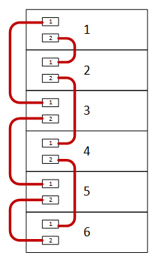
sw1 port 2 - sw2 port1
sw2 port 2 - sw3 -port1
sw3 port 2 - sw4 -port1
sw4 port 2 - sw5 -port1
sw5 port 2 - sw6 -port1
sw6 port 2 - sw1 -port1
Also make stack master/backup sw2-3-4-5 ( if sw1 and sw6 is where your uplinks reside)
Please rate and mark as an accepted solution if you have found any of the information provided useful.
This then could assist others on these forums to find a valuable answer and broadens the community’s global network.
Kind Regards
Paul
Discover and save your favorite ideas. Come back to expert answers, step-by-step guides, recent topics, and more.
New here? Get started with these tips. How to use Community New member guide
